Communication and sharing promote growth
Joining Hands for Development!

In the actual production, assembly and use process, the insulation withstand voltage failure of battery trays often occurs, like a reef hidden in the rapid development of the new energy industry, threatening the driving safety of vehicles and the reliable operation of the energy storage system. This article attempts to analyze the typical failure modes based on manufacturing practice, in order to provide some superficial references for relevant practitioners and help industry colleagues jointly explore effective ways to improve the insulation withstand voltage performance of battery trays.
Part 3 -Common failure analysis

Figure 1 Insulation withstand voltage test
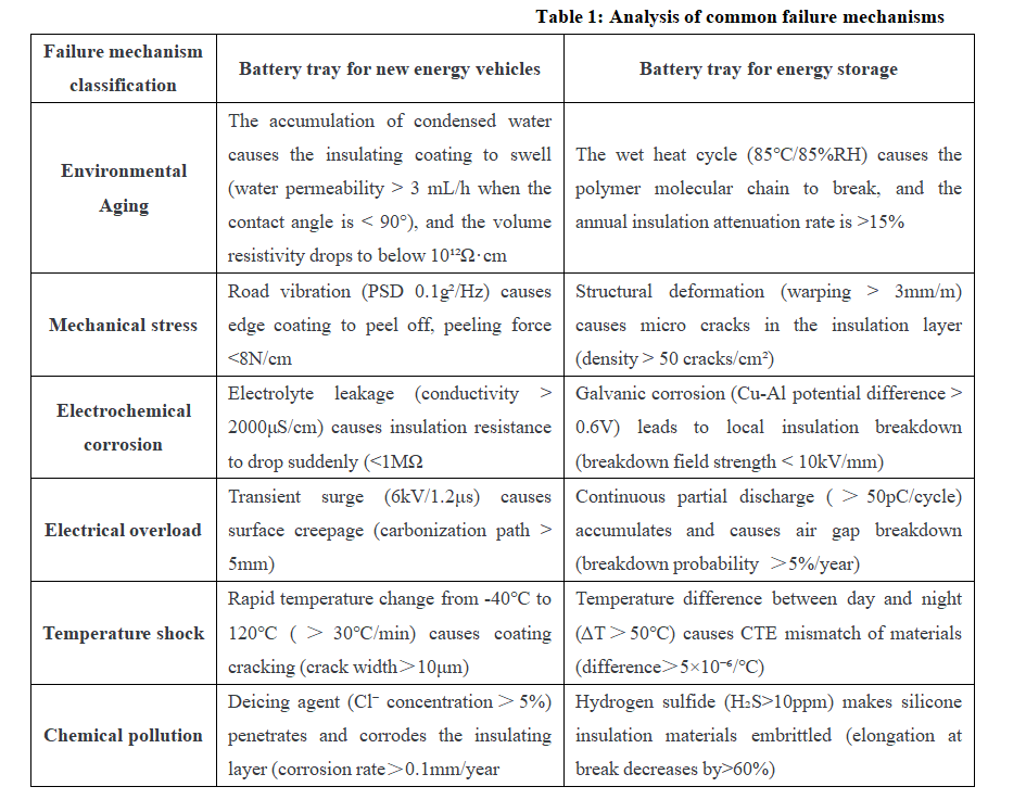
1- Analysis of common failure mechanisms
The application scenarios of battery trays for energy storage and new energy vehicles are different, resulting in both commonalities and differences in insulation withstand voltage requirements and failure conditions, as follows:
a. Differences
Dynamic load: New energy vehicles need to deal with high-frequency mechanical vibrations of 20-2000Hz, while energy storage systems mainly face long-term static deformation, with cumulative deformation time exceeding 10 years.
Voltage level: The insulation withstand voltage of new energy vehicle battery trays must reach 3000VDC and above (based on GB 38031), while energy storage systems require insulation withstand voltage of 4200VAC and above (based on IEC 61439).
Failure acceleration factor: New energy vehicles generate thermal stress due to more than 2000 charge and discharge cycles per year, which accelerates insulation failure; energy storage systems operate 24/7, with an average annual operating time of more than 8000 hours, resulting in electrochemical aging, which in turn accelerates insulation failure.
b. Common points
Both need to achieve early warning of insulation failure through insulation resistance monitoring (not less than 100MΩ in cold state and not less than 1MΩ/kV in hot state) and partial discharge control (less than 5pC).

2- Common manufacturing defects that cause insulation withstand voltage failure of battery trays
(1) Insulation withstand voltage construction stage
a. Potential failure and cause analysis
· Material defects:
Cause: Insulation material withstand voltage level is insufficient, aging due to moisture or surface contamination (oil stains, metal debris).
Performance: Low insulation resistance (<100MΩ), leakage current exceeds the standard or direct breakdown during withstand voltage test.
· Process problems:
Cause: Residual metal debris (rough welding/cutting process), uneven thickness of insulation coating or uncured.
Performance: Partial discharge, insulation layer damage causes short circuit.
· Environmental interference:
Cause: High temperature and high humidity cause material moisture absorption and chemical corrosion.
Performance: Insulation performance deteriorates with the environment, and condensed water causes creepage.
· Test errors:
Cause: Wrong test voltage/time setting (such as not in accordance with GB/T 38661 standard), poor grounding.
Performance: Misjudgment of qualified or overvoltage damage to components.
b. Response strategy
· Material optimization: Select moisture-proof materials (such as carbon fiber composite materials) with a withstand voltage of ≥1000V DC and apply anti-fouling coating.
· Process control: Use automated welding/spraying equipment and set up a clean workshop.
· Environmental management: Install temperature and humidity monitoring and pre-dry materials before construction.
· Test specifications: Segmented testing (500V pre-test + 1000V formal test), calibrate instruments and record data.
(2) Module installation stage
a. Analysis of potential failures and causes
· Assembly error:
Cause: The insulation liner is missing and the bolts are too tight and the insulation layer is damaged.
Performance: Low insulation resistance between the module and the shell, and withstand voltage breakdown.
· Mechanical damage
Cause: Scratches on handling tools, metal debris piercing the insulation film.
Performance: Local short circuit or sudden failure during operation.
· Design compatibility
Cause: Insufficient electrical clearance due to size deviation between the module and the tray.
Performance: Parasitic capacitance causes voltage superposition breakdown.
· Electrical connection hazards:
Cause: Wear and failure of connector seal due to unfixed wiring harness.
Performance: Wear and leakage of high-voltage wiring harness insulation layer.
b. Countermeasures
· Error-proof design: Use positioning pin tooling to prevent missing installation, and customize bolt length to prevent over-tightening.
· Clean operation: Vacuum cleaning before installation, and wrap tools with anti-scratch silicone.
· Tolerance simulation: Verify the matching degree between the module and the tray through CAE to ensure that the gap is ≥10mm.
· Process inspection: After installation, perform random inspection with a megohmmeter (≥100MΩ) and perform segmented withstand voltage test to locate the fault point.
(3) System Integration Phase
a. Potential Failure and Cause Analysis
· Cross-system interface failure:
Cause: Component insulation parameters do not match (such as connector withstand voltage rating differences).
Performance: High-voltage busbar connection breakdown or BMS interference.
· Parasitic capacitance superposition:
Cause: The total parasitic capacitance increases after multiple modules are connected in parallel, and the capacitance rise effect is significant.
Performance: System-level test leakage current exceeds the standard.
· Environmental stress failure:
Cause: Vibration causes insulation fatigue and coolant seeps into the high-voltage interface.
Performance: Insulation resistance decreases periodically during operation.
· Test blind spot:
Cause: Failure to simulate real working conditions (high temperature/vibration/humidity).
Performance: Passed in the laboratory but failed in actual operation.
b. Countermeasures
· Compatibility design: Unify supplier component standards.
· Parasitic capacitance control: Add polyimide isolation layer and optimize layout through SPICE simulation.
· Working condition simulation test: perform "-40℃~85℃ cycle + 5Hz~200Hz vibration + withstand voltage" composite test.
· Intelligent monitoring: integrated online insulation monitoring module, AI predicts potential risks.
3-Insulation withstand voltage test
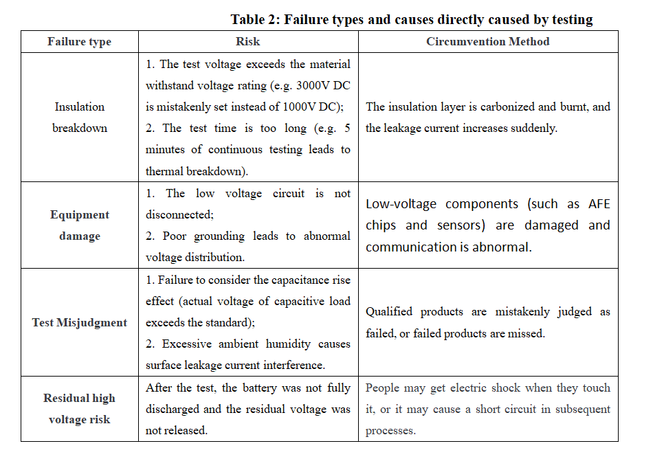
Insulation withstand voltage test is both a safety measure and a possible cause of failure. The insulation withstand voltage test itself may cause failure due to improper operation, equipment problems or design defects, and even cause secondary damage to the device under test.
(1) Common types of failure during the test

(2) The response strategies are as follows:
a. Precise control of test parameters
· Voltage and time: set according to standards; enable dynamic compensation algorithm for capacitive loads (such as battery modules) to suppress the capacity increase effect.
· Leakage current threshold: set according to equipment specifications (such as ≤10mA) and distinguish between DC/AC modes (DC testing requires a lower threshold).
b. Equipment and operation specifications
· Instrument calibration: The withstand voltage tester is calibrated every 6 months, and the high-voltage line insulation layer is visually inspected daily.
· Safe operation: forced disconnection of low-voltage circuits before testing; use robotic arms or automatic fixtures to avoid manual contact with high-voltage areas.
c. Failure prevention and repair
· Segmented testing: test complex systems in modules (such as testing the high-voltage bus first, then testing the module insulation) to locate the breakdown point.
· Failure repair: use epoxy resin to fill the damaged area after breakdown, and after repair, it is necessary to pass the full voltage gradient test again (such as 500V→1000V step pressure).
d. Environment and data management
· Environmental control: Start the dehumidifier when the humidity in the test area is greater than 75%, or delay the test until the environment meets the standard.
· Data traceability: Record the test voltage, leakage current curve, and environmental parameters, and use the MES system to associate the production batch number.
We will regularly update you on technologies and information related to thermal design and lightweighting, sharing them for your reference. Thank you for your attention to Walmate.