



Resource Center
Communication and sharing promote growth
Joining Hands for Development!
Communication and sharing promote growth
Joining Hands for Development!


Three-stage leak testing has become standard practice in the industry, but just because it’s common doesn’t mean everyone understands the rationale.
Ask a quality engineer why a battery tray needs three leak tests, and the most common reply will likely be: “One test for the flow channel, one for the enclosure, and one before final assembly.”
That answer is not wrong, but it doesn’t get to the root of the matter.
Today we’re going to lay out the full logic behind it—especially for heavy-duty truck and mining truck battery trays, which are large, long-life, high-reliability components. If a sealing defect in manufacturing slips through to final assembly, the cost is far higher than for ordinary parts.
1. Why not wait until the very end and run just one leak test?
Let’s tackle the most basic question first: Could we complete all manufacturing and then perform a single leak test?
The answer is: Yes, you can, but after testing you’ll likely have no idea what to do next. There are three reasons.
First, the signals are mixed, making it impossible to tell where the leak originates.
Before final assembly, the product is already a combination of the flow channel and the enclosure. During pressurization, gas can escape from the flow channel welds into the enclosure cavity, from the enclosure welds to the outside, or through sealing surfaces and mounting holes. The test equipment can only tell you “there is a leak”, not which weld, which process step, or which location caused it.
If it fails, everything from the first operation to the last becomes suspect.
Second, rework costs have already multiplied several times over.
If a flow channel leak is detected at the flow‑channel stage, it can be reworked with a direct weld repair, at the lowest cost.
If you wait until after the enclosure is formed, you need to disassemble reinforcements and work inside the structure—costs multiply by 5 to 10 times.
If you wait until after final assembly? Removing cells, disassembling the enclosure, and reassembling can drive costs up by 100 times or more—and in many cases there is no rework path left, only scrapping.
Third, the inspection window has already closed.
Right after flow‑channel welding, all welds are exposed and leak detectors can directly cover the entire surface. This is the cleanest inspection window.
But once the flow channel is welded into the enclosure, reinforcements are added, and machining is done, it becomes enclosed inside. If you test at that point, gas can move between multiple internal cavities, and even if the instrument alarms, you cannot tell whether the signal comes from the flow channel or the enclosure.
Once the inspection window closes, the signal becomes contaminated. Once the rework window closes, costs spiral out of control.
The entire logic of the three‑step approach is to complete the necessary tests before these two curves cross.
2. So why three tests, not two or four?
Because the manufacturing process provides three irreversible inspection windows.
The production sequence of a battery tray is: the flow channel is formed first → then it is welded into the enclosure → finally it enters final assembly. The inspection windows open and close sequentially with the manufacturing sequence. The three‑step approach is passively dictated by the production sequence; it is not an arbitrary choice.
Inspection Window 1: Flow channel leak test—formed first, tested first
The flow channel is the first component in the battery tray to complete welding.
At this point, the test environment is cleanest: all welds are exposed, with no enclosure interference, so the leak signal is 100% from the flow channel itself. The conclusion is unambiguous: pass means pass, and failure means the leak point can be pinpointed.
Why must it be tested at Window 1?
Because the flow channel’s inspection window closes first. Once it is welded into the enclosure, you can never again obtain an independent, interference‑free leak signal for the flow channel.
Test objects: flow channel weld seams, water nozzle weld seams
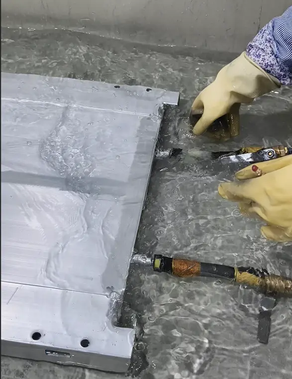
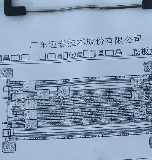
Test node: immediately after flow‑channel welding, with rechecks after subsequent critical processes
Inspection Window 2: Enclosure leak test—structure complete, system verified
A passing flow channel does not guarantee a passing enclosure.
Frame welding, structural component installation, machining, connector welding—each process introduces new variables. Welding heat input causes distortion, machining stress affects flatness, and mounting hole machining may create micro‑cracks. These risks are cumulative consequences of the processes; they do not exist at the flow‑channel stage and cannot be detected there.
At this point, the enclosure is integrally formed but external accessories have not yet been installed. Although the test signal is more complex than at Window 1, interference sources are still controllable—no cells, top cover, piping, or other additional components that add extra noise.
Why must it be tested at Window 2?
The enclosure leak test window exists in the interval between structural completion and installation of external accessories. Test too early: the structure is incomplete, so you cannot test everything. Test too late: accessories are installed, contaminating the signal.
Test objects: overall weld seams, sealing surfaces, mounting holes
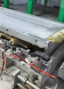
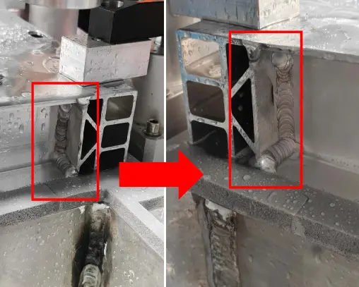
Test node: staged verification during enclosure manufacturing
Inspection Window 3: Pre‑final‑assembly leak test—combined verification, final release
The flow channel has been independently tested, and the enclosure has been staged‑tested. But the combined assembly’s sealing integrity has not yet been verified—and combined assemblies can have unique leak paths, such as the interface between the flow channel and the enclosure.
From enclosure completion to final assembly, the product undergoes handling, turning, storage, and fixturing. These operations do not generate welding heat input, but they may introduce mechanical stress or minor deformation.
Pre‑final assembly is the last clean inspection window. Cells, BMS, and top cover have not yet been installed, and the main structure is in its final verification state.
Why must it be tested at Window 3?
If you skip this test, you are carrying the cumulative errors of all previous processes into the final assembly line. If a leak is found after final assembly is complete, there is no rework space left.
Test objects: flow channel system and enclosure as a combined unit, verified in parallel
Test node: after main structure completion, before final assembly starts
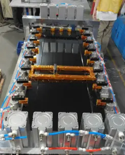
A quick comparison of the three steps
Step 1: Flow channel leak test | Step 2: Enclosure leak test | Step 3: Pre‑final assembly leak test | |
Test Object | Flow channel welds, water nozzle welds | Overall welds, sealing surfaces, mounting holes | Flow channel + enclosure as a combined unit |
Window Status | Cleanest, no interference | Complete structure, no external accessories | Main structure complete, no external components |
Consequence of failure | Rework or scrap the flow channel part | Rework localized enclosure structure | Overall assessment, high rework cost |
Finally
The three‑step approach is not redundant testing; it is chasing the inspection windows as they open. Test the flow channel when it is independent, test the enclosure when it is formed, and test the main structure before final assembly—each step completes verification at the cleanest signal stage and the lowest cost, rather than leaving everything to a final reckoning.
If you are evaluating a battery tray supplier for electric heavy‑duty trucks or mining trucks, feel free to request our product catalog or schedule a factory visit
We will regularly update you on technologies and information related to thermal design and lightweighting, sharing them for your reference. Thank you for your attention to Walmate.
Scan to follow
测试测试测试测试测试测试测试测试测试测试测试测试测试测试测试测试测试测试测试测试测试测试测试测试测试测试测试测试测试测试测试测试测试测试测试测试测试测试测试测试测试测试测试测试测试测试测试测试测试测试测试测试测试测试测试测试测试测试测试
测试测试测试测试测试测试测试测试测试测试测试测试测试测试测试测试测试测试测试测试测试测试测试测试测试测试测试测试测试测试测试测试测试测试测试测试测试测试测试测试测试测试测试测试测试测试测试测试测试测试测试测试测试测试测试测试测试测试测试
测试测试测试测试测试测试测试测试测试测试测试测试测试测试测试测试测试测试测试测试测试测试测试测试测试测试测试测试测试测试测试测试测试测试测试测试测试测试测试测试测试测试测试测试测试测试测试测试测试测试测试测试测试测试测试测试测试测试测试
测试测试测试测试测试测试测试测试测试测试测试测试测试测试测试测试测试测试测试测试测试测试测试测试测试测试测试测试测试测试测试测试测试测试测试测试测试测试测试测试测试测试测试测试测试测试测试测试测试测试测试测试测试测试测试测试测试测试测试
测试测试测试测试测试测试测试测试测试测试测试测试测试测试测试测试测试测试测试测试测试测试测试测试测试测试测试测试测试测试测试测试测试测试测试测试测试测试测试测试测试测试测试测试测试测试测试测试测试测试测试测试测试测试测试测试测试测试测试
测试测试测试测试测试测试测试测试测试测试测试测试测试测试测试测试测试测试测试测试测试测试测试测试测试测试测试测试测试测试测试测试测试测试测试测试测试测试测试测试测试测试测试测试测试测试测试测试测试测试测试测试测试测试测试测试测试测试测试
测试测试测试测试测试测试测试测试测试测试测试测试测试测试测试测试测试测试测试测试测试测试测试测试测试测试测试测试测试测试测试测试测试测试测试测试测试测试测试测试测试测试测试测试测试测试测试测试测试测试测试测试测试测试测试测试测试测试测试
测试测试测试测试测试测试测试测试测试测试测试测试测试测试测试测试测试测试测试测试测试测试测试测试测试测试测试测试测试测试测试测试测试测试测试测试测试测试测试测试测试测试测试测试测试测试测试测试测试测试测试测试测试测试测试测试测试测试测试
测试测试测试测试测试测试测试测试测试测试测试测试测试测试测试测试测试测试测试测试测试测试测试测试测试测试测试测试测试测试测试测试测试测试测试测试测试测试测试测试测试测试测试测试测试测试测试测试测试测试测试测试测试测试测试测试测试测试测试
测试测试测试测试测试测试测试测试测试测试测试测试测试测试测试测试测试测试测试测试测试测试测试测试测试测试测试测试测试测试测试测试测试测试测试测试测试测试测试测试测试测试测试测试测试测试测试测试测试测试测试测试测试测试测试测试测试测试测试
测试测试测试测试测试测试测试测试测试测试测试测试测试测试测试测试测试测试测试测试测试测试测试测试测试测试测试测试测试测试测试测试测试测试测试测试测试测试测试测试测试测试测试测试测试测试测试测试测试测试测试测试测试测试测试测试测试测试测试
测试测试测试测试测试测试测试测试测试测试测试测试测试测试测试测试测试测试测试测试测试测试测试测试测试测试测试测试测试测试测试测试测试测试测试测试测试测试测试测试测试测试测试测试测试测试测试测试测试测试测试测试测试测试测试测试测试测试测试
测试测试测试测试测试测试测试测试测试测试测试测试测试测试测试测试测试测试测试测试测试测试测试测试测试测试测试测试测试测试测试测试测试测试测试测试测试测试测试测试测试测试测试测试测试测试测试测试测试测试测试测试测试测试测试测试测试测试测试
测试测试测试测试测试测试测试测试测试测试测试测试测试测试测试测试测试测试测试测试测试测试测试测试测试测试测试测试测试测试测试测试测试测试测试测试测试测试测试测试测试测试测试测试测试测试测试测试测试测试测试测试测试测试测试测试测试测试测试
测试测试测试测试测试测试测试测试测试测试测试测试测试测试测试测试测试测试测试测试测试测试测试测试测试测试测试测试测试测试测试测试测试测试测试测试测试测试测试测试测试测试测试测试测试测试测试测试测试测试测试测试测试测试测试测试测试测试测试
测试测试测试测试测试测试测试测试测试测试测试测试测试测试测试测试测试测试测试测试测试测试测试测试测试测试测试测试测试测试测试测试测试测试测试测试测试测试测试测试测试测试测试测试测试测试测试测试测试测试测试测试测试测试测试测试测试测试测试
测试测试测试测试测试测试测试测试测试测试测试测试测试测试测试测试测试测试测试测试测试测试测试测试测试测试测试测试测试测试测试测试测试测试测试测试测试测试测试测试测试测试测试测试测试测试测试测试测试测试测试测试测试测试测试测试测试测试测试
测试测试测试测试测试测试测试测试测试测试测试测试测试测试测试测试测试测试测试测试测试测试测试测试测试测试测试测试测试测试测试测试测试测试测试测试测试测试测试测试测试测试测试测试测试测试测试测试测试测试测试测试测试测试测试测试测试测试测试
测试测试测试测试测试测试测试测试测试测试测试测试测试测试测试测试测试测试测试测试测试测试测试测试测试测试测试测试测试测试测试测试测试测试测试测试测试测试测试测试测试测试测试测试测试测试测试测试测试测试测试测试测试测试测试测试测试测试测试
测试测试测试测试测试测试测试测试测试测试测试测试测试测试测试测试测试测试测试测试测试测试测试测试测试测试测试测试测试测试测试测试测试测试测试测试测试测试测试测试测试测试测试测试测试测试测试测试测试测试测试测试测试测试测试测试测试测试测试