




Resource Center
Communication and sharing promote growth
Joining Hands for Development!
Communication and sharing promote growth
Joining Hands for Development!


Energy storage batteries increase capacity by enlarging the physical dimensions of cells (e.g., from 314Ah to 587Ah). Given unchanged materials and voltage platforms, the increase in size and weight does not alter the Pack's electrical architecture—instead, it channels all pressure onto the structural mechanical loads and insulation safety margins.
A fundamental question emerges: as the "physical energy" of cells expands dramatically, has the electrical safety design logic we rely on been upgraded in tandem?
I. Core Premise: The "Unchanged" Electrical Architecture
Two fundamental points must first be clarified:
First, under a typical 1P104S series architecture with 8 modules (13S per module), the Pack's nominal system voltage and the statutory baseline insulation withstand voltage rating have not undergone significant changes.
Second, the root cause of all cascading effects is the dramatic change in cell physical scale, which drives near-exponential growth in the Pack's total mass, volume, total energy storage (kWh), and the internal expansion stress during cell cycling. The electrical system must achieve full-lifecycle reliable operation on this entirely new, heavier, and more "stressed" physical foundation.
II. Core Impact on the Electrical Structural System: From "Static Connections" to "Dynamic Load-Bearing Systems"
The enlargement of cell physical dimensions first elevates the electrical connection system from a purely conductive interface to a critical mechanical load-bearing and stress-coordination node.
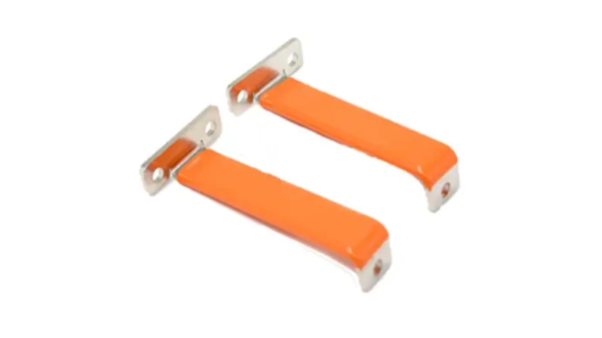
Figure 1: Copper busbar for energy storage systems
a. Electrical Connection Points Upgraded to Critical Mechanical Interfaces
Cell weight increase and stronger volumetric expansion forces subject terminal connection points to shear and fatigue stresses far exceeding previous levels. The primary design task for connections has shifted to ensuring mechanical robustness, requiring simultaneous enhancement of connection piece cross-sectional area, welding strength, or bolt anti-loosening grade.
Heavier modules generate stronger dynamic stresses under vibration, requiring busbar supports with higher rigidity, and connection pieces must incorporate flexible transition sections to absorb micro-deformation and prevent fatigue fracture.
b. Busbar and High-Voltage Harness Layout and Fixation Restructuring
The increased size of cells and modules severely constrains internal enclosure space, making routing paths for high-voltage busbars and harnesses more cramped. To ensure safety clearances, highly integrated and three-dimensionally refined layout designs—such as molded integrated busbars—must be adopted.
Simultaneously, busbar fixation requires systematic reinforcement: using robust metal or high-strength engineering plastic brackets with buffer rubber pads, reliably connected to the enclosure, to build a rigid-flexible fixation system capable of withstanding long-term vibration and impact.
III. Conductive Impact on the Insulation and Safety System: Risk Escalation Driving Defense Enhancement
Although the system voltage has not changed significantly, the increase in cell dimensions—while boosting capacity—introduces two major challenges: internal enclosure space compression eroding safety clearance margins, and the surge in single-cell energy causing exponential increases in potential arc energy, imposing extreme demands on the heat resistance, flame retardancy, and durability of insulation materials. This directly drives insulation and safety design from "compliance-oriented" toward "defense-oriented."
In response, the industry is shifting from passive compliance to proactive reinforcement:
· Implementing platform-level insulation: Applying multifunctional coatings on large metal substrates such as trays and liquid-cooled enclosures to establish a first line of full-domain insulation and corrosion protection.
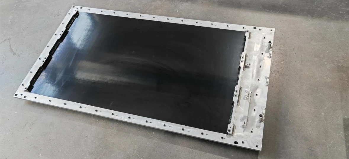
Figure 2: Energy storage battery lower enclosure with multifunctional coating
· Advancing component-level insulation upgrades: Employing integral potting or overmolding for high-voltage busbars and connectors to eliminate short-circuit risks caused by condensation and dust.
· Strengthening thermal runaway protection coordination: Precisely planning pressure relief channels to achieve three-dimensional avoidance from high-voltage routing, and adding protective partitions; simultaneously relying on earlier and more accurate multi-sensor fusion warning to buy time for the BMS to rapidly cut off circuits.
These measures collectively target a single objective: building a multi-layered active defense system that exceeds baseline standards under the dual pressures of physical space constraints and fault energy escalation.
IV. From Design Theory to Product Practice
Large-format cells increase capacity through enlarged dimensions, bringing three core challenges to system safety: heavier loads, stronger expansion, and higher energy risks. This directly drives comprehensive upgrades in battery Packs from structure to safety.
As a key Pack structural component supplier, we clearly observe the specific impact of this trend on products:
a. Enclosures must possess higher stiffness and torsional rigidity to bear the dramatically increased weight and expansion stresses;
b. Battery end plates must combine high strength with insulation, serving as "structural walls" that resist expansion and maintain module stability;
c. Strapping steel bands should be upgraded to prestressed restraint systems combining high-strength materials and precision processes, ensuring the stability of cell stacks throughout long-term cycling.
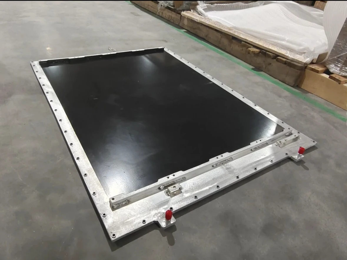
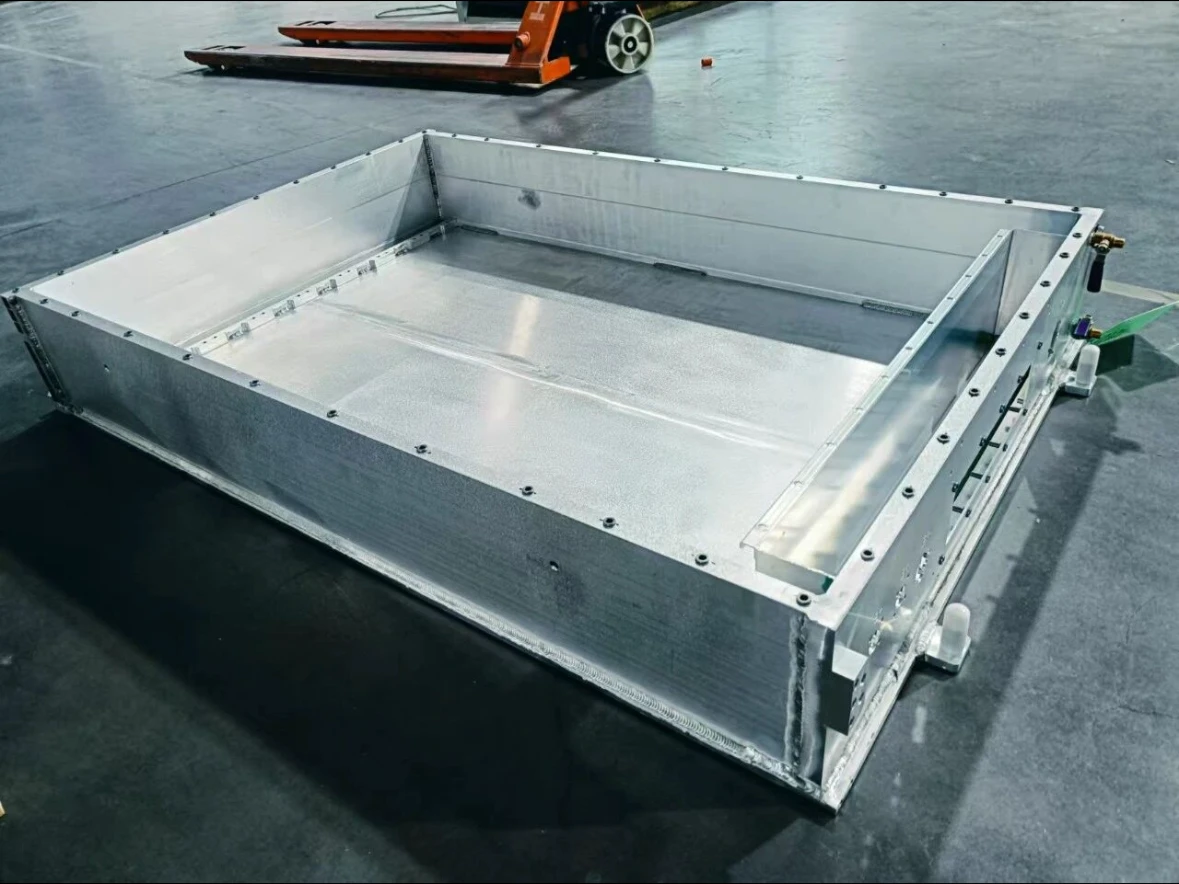
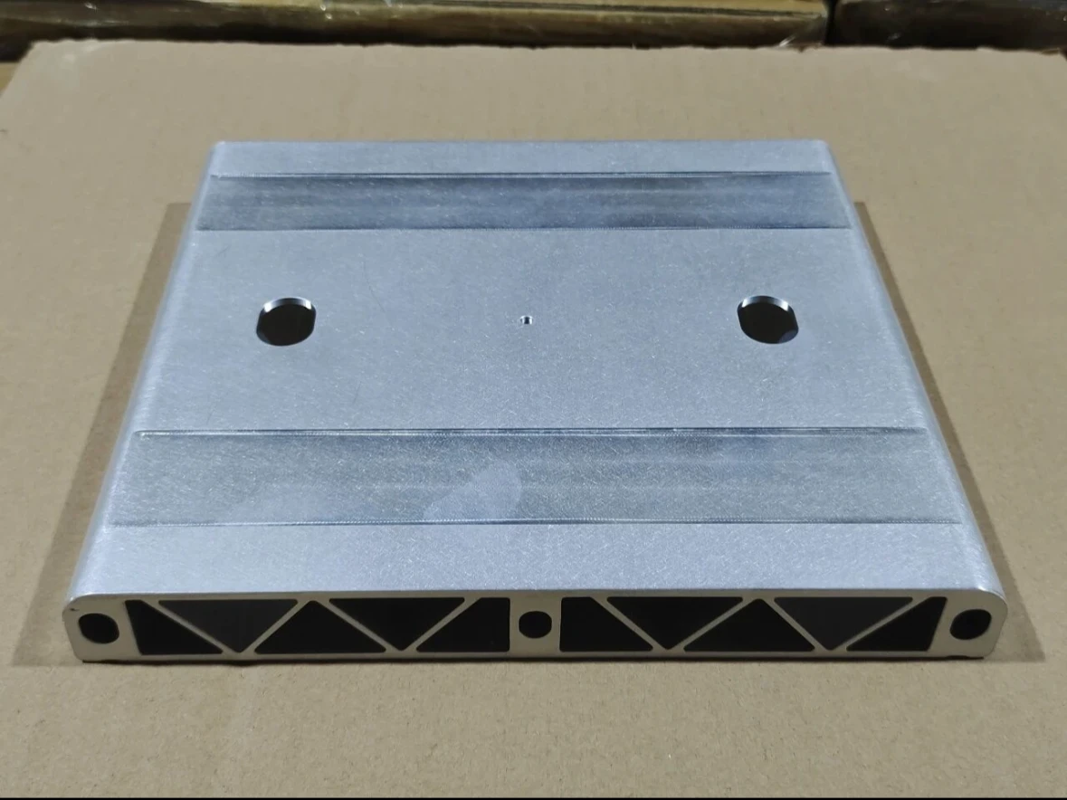
We will regularly update you on technologies and information related to thermal design and lightweighting, sharing them for your reference. Thank you for your attention to Walmate.
Scan to follow
测试测试测试测试测试测试测试测试测试测试测试测试测试测试测试测试测试测试测试测试测试测试测试测试测试测试测试测试测试测试测试测试测试测试测试测试测试测试测试测试测试测试测试测试测试测试测试测试测试测试测试测试测试测试测试测试测试测试测试
测试测试测试测试测试测试测试测试测试测试测试测试测试测试测试测试测试测试测试测试测试测试测试测试测试测试测试测试测试测试测试测试测试测试测试测试测试测试测试测试测试测试测试测试测试测试测试测试测试测试测试测试测试测试测试测试测试测试测试
测试测试测试测试测试测试测试测试测试测试测试测试测试测试测试测试测试测试测试测试测试测试测试测试测试测试测试测试测试测试测试测试测试测试测试测试测试测试测试测试测试测试测试测试测试测试测试测试测试测试测试测试测试测试测试测试测试测试测试
测试测试测试测试测试测试测试测试测试测试测试测试测试测试测试测试测试测试测试测试测试测试测试测试测试测试测试测试测试测试测试测试测试测试测试测试测试测试测试测试测试测试测试测试测试测试测试测试测试测试测试测试测试测试测试测试测试测试测试
测试测试测试测试测试测试测试测试测试测试测试测试测试测试测试测试测试测试测试测试测试测试测试测试测试测试测试测试测试测试测试测试测试测试测试测试测试测试测试测试测试测试测试测试测试测试测试测试测试测试测试测试测试测试测试测试测试测试测试
测试测试测试测试测试测试测试测试测试测试测试测试测试测试测试测试测试测试测试测试测试测试测试测试测试测试测试测试测试测试测试测试测试测试测试测试测试测试测试测试测试测试测试测试测试测试测试测试测试测试测试测试测试测试测试测试测试测试测试
测试测试测试测试测试测试测试测试测试测试测试测试测试测试测试测试测试测试测试测试测试测试测试测试测试测试测试测试测试测试测试测试测试测试测试测试测试测试测试测试测试测试测试测试测试测试测试测试测试测试测试测试测试测试测试测试测试测试测试
测试测试测试测试测试测试测试测试测试测试测试测试测试测试测试测试测试测试测试测试测试测试测试测试测试测试测试测试测试测试测试测试测试测试测试测试测试测试测试测试测试测试测试测试测试测试测试测试测试测试测试测试测试测试测试测试测试测试测试
测试测试测试测试测试测试测试测试测试测试测试测试测试测试测试测试测试测试测试测试测试测试测试测试测试测试测试测试测试测试测试测试测试测试测试测试测试测试测试测试测试测试测试测试测试测试测试测试测试测试测试测试测试测试测试测试测试测试测试
测试测试测试测试测试测试测试测试测试测试测试测试测试测试测试测试测试测试测试测试测试测试测试测试测试测试测试测试测试测试测试测试测试测试测试测试测试测试测试测试测试测试测试测试测试测试测试测试测试测试测试测试测试测试测试测试测试测试测试
测试测试测试测试测试测试测试测试测试测试测试测试测试测试测试测试测试测试测试测试测试测试测试测试测试测试测试测试测试测试测试测试测试测试测试测试测试测试测试测试测试测试测试测试测试测试测试测试测试测试测试测试测试测试测试测试测试测试测试
测试测试测试测试测试测试测试测试测试测试测试测试测试测试测试测试测试测试测试测试测试测试测试测试测试测试测试测试测试测试测试测试测试测试测试测试测试测试测试测试测试测试测试测试测试测试测试测试测试测试测试测试测试测试测试测试测试测试测试
测试测试测试测试测试测试测试测试测试测试测试测试测试测试测试测试测试测试测试测试测试测试测试测试测试测试测试测试测试测试测试测试测试测试测试测试测试测试测试测试测试测试测试测试测试测试测试测试测试测试测试测试测试测试测试测试测试测试测试
测试测试测试测试测试测试测试测试测试测试测试测试测试测试测试测试测试测试测试测试测试测试测试测试测试测试测试测试测试测试测试测试测试测试测试测试测试测试测试测试测试测试测试测试测试测试测试测试测试测试测试测试测试测试测试测试测试测试测试
测试测试测试测试测试测试测试测试测试测试测试测试测试测试测试测试测试测试测试测试测试测试测试测试测试测试测试测试测试测试测试测试测试测试测试测试测试测试测试测试测试测试测试测试测试测试测试测试测试测试测试测试测试测试测试测试测试测试测试
测试测试测试测试测试测试测试测试测试测试测试测试测试测试测试测试测试测试测试测试测试测试测试测试测试测试测试测试测试测试测试测试测试测试测试测试测试测试测试测试测试测试测试测试测试测试测试测试测试测试测试测试测试测试测试测试测试测试测试
测试测试测试测试测试测试测试测试测试测试测试测试测试测试测试测试测试测试测试测试测试测试测试测试测试测试测试测试测试测试测试测试测试测试测试测试测试测试测试测试测试测试测试测试测试测试测试测试测试测试测试测试测试测试测试测试测试测试测试
测试测试测试测试测试测试测试测试测试测试测试测试测试测试测试测试测试测试测试测试测试测试测试测试测试测试测试测试测试测试测试测试测试测试测试测试测试测试测试测试测试测试测试测试测试测试测试测试测试测试测试测试测试测试测试测试测试测试测试
测试测试测试测试测试测试测试测试测试测试测试测试测试测试测试测试测试测试测试测试测试测试测试测试测试测试测试测试测试测试测试测试测试测试测试测试测试测试测试测试测试测试测试测试测试测试测试测试测试测试测试测试测试测试测试测试测试测试测试
测试测试测试测试测试测试测试测试测试测试测试测试测试测试测试测试测试测试测试测试测试测试测试测试测试测试测试测试测试测试测试测试测试测试测试测试测试测试测试测试测试测试测试测试测试测试测试测试测试测试测试测试测试测试测试测试测试测试测试