


We Work
To Understand
Your Project Goals and Outputs
To Understand
Your Project Goals and Outputs

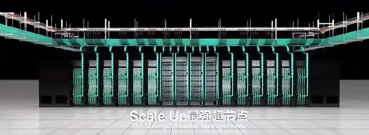
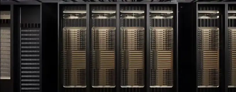
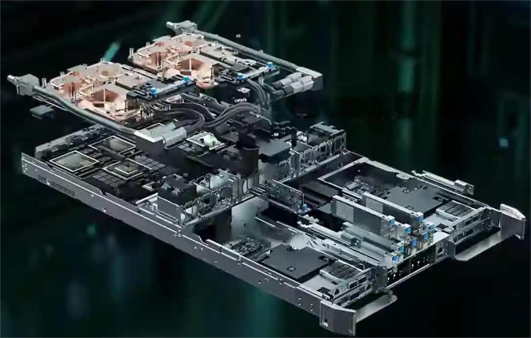
On the path toward Exascale AI computing power, Huawei's CloudMatrix 384 Super Node and NVIDIA's GB200 NVL72 cluster have emerged as two globally prominent technological peaks. They not only represent different hardware integration capabilities but also profoundly reveal two fundamental philosophies for building supercomputing systems.
One is metaphorically described as a "sustained high fever," facing the ultimate thermal challenge of densely packed, steady-state heat dissipation from 384 chips operating at full throttle. The other is likened to "intermittent epileptic seizures," requiring the taming of intense, pulsed heat flows generated when 72 top-tier GPUs work in synchrony. These two different "maladies" ultimately lead to entirely distinct "prescriptions"—namely, thermal solutions—and provide us with a clear view of two core engineering philosophies: deterministic systems engineering versus agile ecosystem innovation. For every company in the supply chain involved, understanding this duel is key to defining their future role.
1-The Root of Core Differences – The "Malady" Determines the "Prescription"
From the outset of design, Huawei and NVIDIA embarked on different paths, directly shaping their distinct thermal source characteristics:
Table 1: Comparison of Thermal Source Characteristics Between Two Technical Approaches

The difference between this "sustained high fever" and "intermittent epileptic seizures" is by no means accidental. It reflects Huawei's choice as a challenger to focus on total system performance, pushing the limits of computing density within a single cabinet at all costs, while NVIDIA, as the leader, faces the task of building an ecosystem that can efficiently collaborate and be widely adopted while maintaining an absolute performance advantage per chip.
2- The Materialization of Engineering Philosophy – Two Liquid Cooling Paths
The two distinct design philosophies are most vividly embodied in their respective liquid cooling solutions, shaping the complete technology stack from the chip to the data center room.
a. Huawei: The Liquid Cooling Practice of Deterministic Systems Engineering
This is a top-down design philosophy born for system-level deterministic goals. Its core lies in treating thermal management as a crucial part of the infrastructure, achieving it through globally integrated, highly reliable engineering, rather than treating it merely as a supporting component.
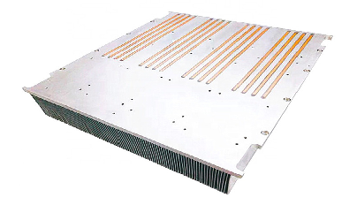
Figure 1: Huawei Ascend 384 Super Node
· Chip-level Precision Engineering and Reliable Connection: To ensure efficient heat transfer from the chip to the cold plate, Huawei focuses on engineering optimization of interface materials. While public information shows its advanced patent reserves in this field (e.g., using high-sphericity silicon carbide fillers), its specific implementation within the super node remains undisclosed. It is certain that its solution inevitably pursues extremely low interfacial thermal resistance and long-term reliability to meet the "sustained high fever" challenge.
· System-level Redundancy and Intelligent Control: Adopts redundant designs, such as ring-shaped liquid supply, and develops in-house Liquid Cooling Thermal Management Units (TMUs) as the system's "central nervous system." This controller enables zero-second switching between pipelines and utilizes AI for failure prediction, ensuring the determinism and reliability of the thermal dissipation chain in a software-defined manner—a hallmark of its systems engineering thinking.
· Infrastructure Convergence ("Cooling-Power Integration"): At the cabinet level, the Liquid Distribution Unit (LDU) and the High-Voltage Power Distribution Unit (PDU) are physically integrated and managed uniformly. This "cooling-power integrated" design is the ultimate engineering response to the ultra-high power density per cabinet, simplifying deployment and improving energy efficiency (lowering PUE). It represents the physical manifestation of its deterministic design philosophy.
b. NVIDIA: The Liquid Cooling Framework of Agile Ecosystem Innovation
This is a design philosophy centered on the GPU, empowering the global ecosystem through the definition of open standards. Its core is to provide a validated "blueprint," lowering the application barrier for the entire industry and enabling efficient, flexible, and large-scale deployment.
· Chip-level Standardization and Reference Design (VRD): NVIDIA provides detailed thermal reference designs for its GPUs (e.g., the Blackwell series), explicitly defining the performance interfaces for the cold plate, including physical dimensions, Thermal Design Power (TDP), flow rate, and pressure drop. This essentially provides a "standard answer" for all cooling vendors, encapsulating complexity within standardized components and ensuring compatibility and a quality baseline for foundational parts.
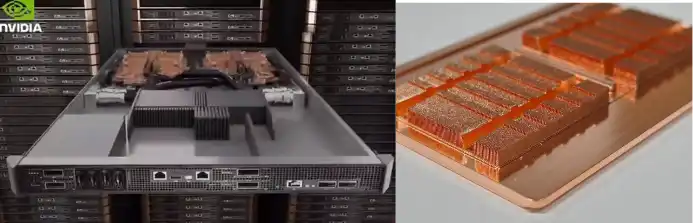
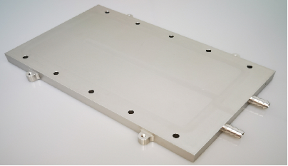
Figure 2: NVIDIA Server Module and Micro-channel Cold Plate
· Ecosystem-level Collaboration and Solution Certification: Engages in deep collaboration with top thermal management and infrastructure vendors like Vertiv and Boyd to jointly develop and certify cabinet-level liquid cooling solutions. For instance, Vertiv's Tier 2 Ready cabinet solution is a pre-validated product developed based on NVIDIA's blueprint, enabling data center operators to rapidly obtain a plug-and-play liquid-cooled cluster as easily as procuring standard equipment.
· Digital Twin Enablement and Deployment Acceleration: Leveraging the NVIDIA Omniverse platform, it provides digital twin and simulation tools for data center liquid cooling systems. Customers can design, verify, and optimize cooling solutions in a virtual environment, significantly reducing the cost and risk of physical validation and achieving agility from design to deployment.
To understand these two paths more clearly, their core differences are compared below:

Table 2: Huawei Model vs. NVIDIA Model: Key Differences at a Glance
3- Historical Inspiration and Future Convergence
The competition between these two paths is not an isolated case in the history of technology. It is, in essence, another classic enactment of systemic integrated innovation versus platform-ecosystem innovation. Huawei resembles Apple during the Steve Jobs era, pursuing absolute control over the product experience from top to bottom. In contrast, NVIDIA is more like today's Google Android, driving the prosperity of an entire ecosystem by setting core standards (the Android system / GPU architecture).
For the industry, the future trend is not about one side completely replacing the other but likely involves a degree of convergence:
· In national or enterprise-level projects pursuing ultimate computing power, the allure of "Deterministic Systems Engineering" remains undiminished.
· In the vast commercial cloud computing market, "Agile Ecosystem Innovation" will continue to expand due to its speed and cost advantages.
· Sparks of ingenuity may emerge at the intersection: incorporating deeper customization and collaborative optimization within open ecological standards.
4- Conclusion
Therefore, the cooling debate between Huawei and NVIDIA is fundamentally a contest between two core competitive strengths in the AI era: one side pursues deterministic, extreme performance through the deep integration of systems engineering; the other drives agile industry innovation and rapid proliferation by building open standards and ecosystems. This duel delineates clear path choices for participants in the industrial chain: to act as a "spearhead force," deeply integrated and tackling specific system-level fortresses, or to serve as the "main force," integrating into the ecosystem to explore markets across the vast plains of standardization. Ultimately, victory lies not only in the technology itself but also in the insight into the logic of industrial evolution and a clear definition of one's position in the future blueprint.
We will regularly update you on technologies and information related to thermal design and lightweighting, sharing them for your reference. Thank you for your attention to Walmate.
When the "Large" Size of Battery Cells Becomes a Consensus, the "Strength" of the Pack Becomes the New Battleground
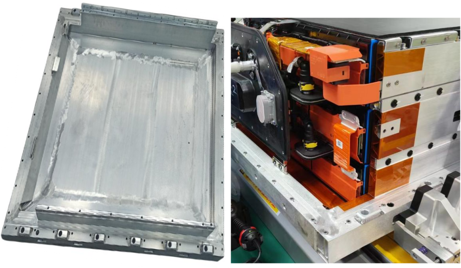
The energy storage industry is entering an era of leapfrogging battery cell capacities, with the shift from 280Ah towards 500Ah+ already underway. While the industry focuses on the "largeness" of cells, the "strength" of the Pack—specifically its mechanical structure's load-bearing and safety mitigation capabilities—is becoming the new competitive focus. Regardless of the evolution in cell chemistry and capacity, the resulting expansion forces, thermal runaway energy, and mechanical loads ultimately must be borne by the Pack's lower enclosure, its mechanical foundation.
From a structural design perspective, this article explores how the Pack lower enclosure can address differentiated mechanical and thermal management demands amidst diverging cell technology pathways, and build sustainably adaptable engineering capabilities.
1- Mechanical Analysis of Three Major Technology Paths: The Triangular Challenge of Load, Heat, and Space
The increase in cell capacity directly alters the boundary conditions for Pack system design. As the "skeleton" and "skin" of the system, the lower enclosure must re-address three fundamental questions:
a. Mechanical Analysis for the 587Ah (High-Integration Path)
Core Demand: Achieving energy density ≥6MWh within a standard 20-foot container has spurred ultra-compact layouts like "4 columns, 8 clusters in total."
Lower Enclosure Challenges:
· Structural Load-Bearing Optimization: With increased overall mass but reduced support points, the enclosure must optimize load transfer paths, balancing overall stiffness with local strength in critical areas to ensure structural stability during transportation and operation.
· Integration of Thermal Management Structure: The liquid cooling system is deeply integrated with the enclosure's base plate and support structures, serving both as the thermal management core and participating in overall load-bearing. The design must ensure the long-term reliability of cooling seals under sustained structural loads and thermal cycling.
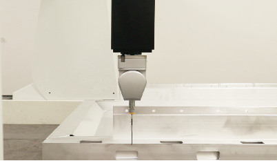
Simulation of Energy Storage Pack Lower Enclosure
· Precise Spatial Coordination: The enclosure must allocate reasonable clearances within the limited space for cell expansion, thermal displacement of electrical connections, fire suppression piping, etc., enabling the reliable coexistence of all subsystems within the compact layout.
b. Thermo-Mechanical and Structural Response Analysis for the 684Ah (Ultra-Large Capacity Path)
Core Demand: Minimizing cost per Wh by maximizing single-cell capacity, which introduces physical centralization effects.
Lower Enclosure Challenges:
· "Focal Point" Effect of Expansion Force: The expansion force of a single cell does not increase linearly with capacity but nearly exponentially. The internal frame of the enclosure requires a more robust and uniform "restraint system" to distribute the concentrated expansion stress across the entire structure, avoiding local plastic deformation.
· "Uniformity" Dilemma in Thermal Management: Larger heat-generating bodies require more efficient heat conduction paths. The material, thickness of the enclosure's base plate, and the design of the contact interface with the cell bottom (such as the compression ratio setting for thermal pads) become critically important. During thermal runaway, the larger energy release places higher demands on the directional venting capability of pressure relief channels and the flame-retardant duration of internal fire barriers.
· Structural Response to Concentrated Weight: Heavier individual cells alter the overall vibration modes of the Pack. The lower enclosure requires renewed fatigue simulation to prevent resonance at specific frequencies leading to fastener loosening or structural cracks.
c. Manufacturing Adaptability Explanation for the 392Ah (Robust Transition Path)
Core Demand: Focuses on balancing performance, cost, and delivery efficiency, providing a thoroughly validated solution to the market.
Lower Enclosure Challenges:
· Stable Realization of Mature Solutions: Ensuring product consistency through strict process control based on a verified design and manufacturing system, supporting rapid and stable mass production schedules.
· Deep Supply Chain Collaboration: Leveraging an established supply system to continuously enhance the product's comprehensive cost competitiveness through material selection, process optimization, and scaled procurement.
2- Engineering Thinking to Address Divergence
Confronted with multiple technology pathways, lower enclosure suppliers cannot rebuild their technical systems for each path. The real solution lies in platform-based, precise response—efficiently adapting to different requirements through scalable, modular design.
a. Focusing on Common Physical Principles and Collaborative Models
Cell iteration follows stable physical laws. We have established a collaborative evaluation process based on core parameters, integrating materials and structural data to rapidly assess the feasibility of new cells. This enables early identification of matching risks, helping to converge design directions and reduce late-stage iterations.

587Ah Energy Storage Battery Pack Lower Chassis
b. Building a Flexible System of "Standardized Interfaces + Configurable Modules"
To address the customization demands arising from technological divergence, we have established a design system with clearly defined interface standardization and internally configurable modules:
· Unified External Interfaces: Installation positioning to the energy storage container, electrical penetration interfaces, cooling system connection points, etc., all strictly adhere to common industry specifications, ensuring compatibility and assembly consistency at the system level.
· Configurable Internal Structure: We offer a series of internal support components and thermal management integration solutions that can be flexibly combined according to cell dimensions and layout.
· Thermal Management Integration Module: The thermal management module adopts a modular design, focusing on optimizing temperature rise control and cell temperature uniformity. It can flexibly adapt to the thermal management needs of different technology paths.
c. Implementing Flexible Production Lines with "Design for Manufacturability"
To match the diversity of technology paths, our manufacturing system is organized around an extensible base platform and modular assembly:
· Base Enclosure Platform Manufacturing: Ensures the precision and consistency of the main structure, providing a reliable carrier for different configurations.
· Modular Assembly Units: Supports flexible selection and assembly of corresponding internal support and thermal management modules based on cell size and layout. Through this setup, we can efficiently switch production for products of different technology paths on the same line, assisting customers in managing supply chain and delivery challenges posed by parallel multi-path development.
3- Redefining the Value of the Lower Enclosure: From Passive Bearing to Active Enablement
The lower enclosure is transitioning from a passive container to a critical system-enabling component, directly impacting safety, energy density, and total lifecycle cost:
a. Safety-Critical Load-Bearing Structure: By providing reliable structural channels and mounting foundations for system-level pressure relief and fire barriers, it works in concert with thermal runaway propagation control to build multi-tiered safety protection.
b. Energy Density Enabler: Lightweight, high-strength design reduces its own weight and spatial footprint, reserving more performance margin for the battery cells and cooling system.
c. Long-Term Reliability Assurance: Structural integrity and fatigue endurance design support the system in withstanding continuous challenges like long-term cycling and transportation vibrations.
4- Conclusion: Building a Bridge Between Diverging Upstream and a Determined Downstream
As battery cell technology evolves, energy storage systems relentlessly pursue safety, high density, and low cost. The lower enclosure must provide a reliable and adaptable foundational support, utilizing modularity and flexible manufacturing to accommodate different technology pathways. Industry competition is shifting towards system-level engineering, where the Pack enclosure serves as a pivotal link.

We will regularly update you on technologies and information related to thermal design and lightweighting, sharing them for your reference. Thank you for your attention to Walmate.
Over the decades of data center development, air cooling technology has consistently been the mainstream choice. However, the launch of NVIDIA's GB200 series products is decisively shattering this equilibrium. As computational density reaches new heights, traditional cooling methods can no longer meet the demands. Liquid cooling technology is now formally stepping from behind the scenes to center stage, becoming the critical infrastructure supporting AI computing power.
1- Fundamental Shifts on the Demand Side
a. Power Density Breaks the Critical Point
The power density of a GB200 NVL72 rack is projected to exceed 30 kW per rack, a figure far beyond the 15-20 kW thermal dissipation limit of traditional air cooling. This signifies:
· An Inevitable Choice of Technology Path: Liquid cooling transitions from "worth considering" to the "only viable option."
· A Qualitative Change in Market Scope: Each GB200 deployment represents a definitive demand for liquid cooling.
· A Significant Increase in Value: The liquid cooling system for a single rack reaches a value level of several hundred thousand RMB.
b. Reliability Requirements Are Upgraded
As the compute density per rack increases, the business value it carries grows exponentially. The reliability of the liquid cooling system is directly linked to:
· Business Continuity: A single cooling failure could lead to computing power losses worth millions.
· System Lifespan: For every 10°C temperature increase, the lifespan of electronic components is halved.
· Performance Stability: Cooling efficiency directly impacts whether chips can sustain peak performance.
2- Comprehensive Enhancement of Technical Requirements
a. Leap in Cooling Efficiency Demands
The GB200 places unprecedented demands on the cooling system:
· Doubling of Heat Transfer Performance: The thermal conductivity of cooling plates needs to be 3-5 times that of traditional solutions.
· Order-of-Magnitude Reduction in Contact Thermal Resistance: Requires contact thermal resistance to be reduced by one order of magnitude.
.")
Figure 1 - Microchannel cold plate
b. Flow Rate Precision Control
· Requires flow control accuracy within ±1%.
· Supports dynamic flow rate adjustment to adapt to different load conditions.
c. Temperature Uniformity
· Temperature difference across the chip surface must be controlled within 5°C.
· Prevents local hotspots from affecting system stability.
3- Leap in System Integration Complexity
Liquid cooling systems have evolved from simple component supply to complex system engineering:
a. Traditional Model:
· Provision of standardized cooling plates.
· Simple piping connections.
· Basic monitoring functionality.
b. The GB200 Era:
· Rack-level liquid cooling architecture design.
· Intelligent flow distribution systems.
· Real-time health status monitoring.
· Predictive maintenance capabilities.

Figure 2 - NVIDIA GB200 cabinet
4- Comprehensive Elevation of Competitive Barriers
In the new market environment, companies must now clear significantly higher thresholds:
a. Technical Barriers
Liquid cooling companies must break through the limitations of single disciplines and build a comprehensive, cross-disciplinary technological system. The deep integration of multi-disciplinary technologies such as microchannel design, materials science, and fluid dynamics has become the basic entry requirement. Furthermore, capabilities in chip-level thermal simulation and optimization truly test a company's profound technical accumulation. This is no longer merely a matter of simple process improvement, but a systemic engineering challenge requiring long-term R&D investment.
b. Certification Barriers
The industry certification system is becoming increasingly stringent. Companies must not only pass the rigorous reliability tests mandated by server manufacturers but also obtain technical certification from the original chip manufacturers. This dual certification requirement not only validates a product's technical performance but also rigorously tests a company's quality management systems and its ability to ensure stable, continuous supply. It has become an essential passport for entering the core supply chain.
c. Service Barriers
As liquid cooling systems are upgraded to core subsystems, service capability has become a critical competitive factor. Companies must establish nationwide rapid-response networks and build professional, 24/7 operational and maintenance systems. This service capability demands not just the timeliness of technical support but also comprehensive end-to-end service solutions encompassing preventative maintenance and emergency response, truly positioning the company as a trustworthy partner for its clients.
We will regularly update you on technologies and information related to thermal design and lightweighting, sharing them for your reference. Thank you for your attention to Walmate.
In the history of computing architecture evolution, certain moments do not arrive silently. The launch of NVIDIA's GB200 NVL72 is one such moment—it is not merely a new product, but a complete reconceptualization of the server itself.
For three decades, a "server" has consistently meant a standardized chassis unit: containing a motherboard, CPU, memory, storage drives, and expansion cards, interconnected via industry-standard interfaces. We measure it in "U"s, rack and stack it in cabinets, and connect to it over networks. However, the emergence of the GB200 NVL72 is fundamentally dissolving this long-standing definition at its core.
Its essence is no longer "a server," but rather a "computer" that takes the form of an entire rack. Traditional server components are deconstructed and then reintegrated on a grander scale—via NVLink-C2C, liquid cooling, and rack-scale power management—into an indivisible computational whole. This is no simple upgrade; it is a profound paradigm shift.
1- What is a "Server"? The Answer to This Question is Changing
For three decades, our understanding of a server has been a standardized chassis: inside resides a motherboard, CPU, memory, storage drives, and expansion cards, all adhering to industry standards, allowing for arbitrary replacement and upgrade.
But the change brought by the GB200 is fundamental:
· The computational heart is no longer discrete CPUs and GPUs, but the GB200 Superchip—a holistic entity deeply integrating a CPU and a GPU.
· Interconnect no longer relies on standard PCIe slots, but on customized NVLink backplanes.
· Cooling is no longer an optional accessory, but an integrated liquid cooling system.
· The fundamental unit of deployment has shifted from the "chassis" to the "rack."
The various components of the traditional server have been "torn apart," only to be reassembled and integrated anew at the larger scale of the rack. This is not evolution; it is re-architecture.
Table 1 - Reshaping the Physical Architecture: From "Chassis" to "Rack"
.")
2- The Three Pillars of "Rack-Scale Architecture"
Traditional server design involves balancing trade-offs within a sealed chassis. In contrast, the rack-scale architecture represented by the GB200 approaches cooling, interconnect, power, and management as a complete system, designed holistically at a top level in a new dimension. This is no longer about stacking components, but about deep, system-level integration. This relies on the synergistic innovation of three core pillars working together.
Pillar One: From "Network Interconnect" to "Backplane Bus"
In traditional data centers, servers are independent nodes communicating over a network (like Ethernet). Within the GB200 NVL72, however, the NVLink Fabric functionally replaces the traditional motherboard bus, becoming the "skeleton" connecting all computing units. This shift enables the 72 GPUs in the rack to work in concert like a single, massive GPU, achieving orders-of-magnitude improvements in communication bandwidth and latency.
Pillar Two: Cooling Evolves from "Supporting Facility" to "Core Subsystem"
When computational density progresses from tens of kilowatts per rack to hundreds of kilowatts, traditional air cooling becomes ineffective. Liquid cooling is no longer an optional "supporting facility"; it has become a core subsystem on par with computing and interconnect. Its design directly determines the overall system's performance output and operational stability, making it the key factor in transitioning from "usable" to "high-performance."
Pillar Three: The "Centralization and Re-architecting" of Management and Power
The GB200 adopts rack-level centralized power supply and management. This is not merely about pursuing higher power conversion efficiency, but also a redefinition of system coupling. It brings benefits like simplified cabling and unified management visibility. However, it also expands the potential failure domain from a single server to the entire rack, placing new paradigm-level demands on operational maintenance.
3- The Restructuring and Shift of the Value Chain
The influence of the "rack-scale architecture" represented by the GB200 extends far beyond technology itself, clearly outlining a new industry value chain curve. Traditional value distribution is being disrupted, while new high-value strongholds are quietly forming around system-level integration and hardware-software co-design.
Server Vendors: Strategic Transformation from 'Definers' to 'Integrators'
Traditional server giants, like Dell and HPE, are facing a migration of their core value. The capabilities they once thrived on—motherboard design, system optimization, and standardized manufacturing—are seeing their importance diminish within highly customized, pre-integrated systems like the GB200.
However, new strategic opportunities lie within this crisis:
· Value Moving Upstream: The competitive focus shifts from internal server design to rack-level liquid cooling, power efficiency, and structural layout.
· Value Extending Outward: Core competitiveness extends from hardware manufacturing to professional services for large-scale deployment, cross-platform operational management, and integration capabilities with enterprise IT environments.
This signifies that the role of server vendors is transforming from being "definers" of standard products to becoming "advanced integrators and enablers" of complex systems.
Cloud Vendors' 'Strategic Procurement': Balancing Dependency and Autonomy
For hyperscale cloud vendors, the GB200 is both a strategic necessity and a strategic warning.
· Short-term Tactic: As the ultimate benchmark for computing power, procuring GB200 is an inevitable choice to meet market demand for top-tier AI compute.
· Long-term Strategy: To mitigate supply chain risks and technology lock-in, developing in-house AI chips (like TPU, Trainium, Inferentia) has become a core strategy crucial for future autonomy.
The actions of cloud vendors vividly reflect the complex trade-offs between efficiency and autonomy, and between short-term market needs and long-term control.
The Evolution of End-User Decision-Making: From Evaluating 'Components' to Assessing 'Output'
For end-user technical decision-makers (CTOs, Technical VPs), the procurement evaluation paradigm is undergoing a fundamental shift.
Traditional Procurement Checklist:
· CPU core count and clock speed
· GPU model and quantity
· Memory and storage capacity and speed
Current Strategic Considerations:
· Efficiency Metrics: Performance per watt, total model training time
· Total Cost of Ownership (TCO): Comprehensive cost including hardware, energy consumption, maintenance, and manpower
· Business Agility: Time cycle from deployment to productive output
This shift marks a critical evolution in corporate technology procurement from a cost-center mindset to a productivity-investment mindset.
The GB200 has redefined the compute unit—from the "server" to the "rack." This is not merely a performance upgrade, but a complete paradigm shift in architecture. The pursuit of efficiency has transcended mere component stacking, and the industry value chain is being restructured. In this transformation, the only certainty is this: adapt to it, or be left behind.
A new computational epoch has begun.

We will regularly update you on technologies and information related to thermal design and lightweighting, sharing them for your reference. Thank you for your attention to Walmate.
When your device has multiple core hot spots that are independent of each other, have varying power consumption, or require isolated cooling, traditional single-channel cold plates become inadequate. Multi-loop copper tube embedded cold plates are the key to overcoming this challenge.
1-Why Choose Multi-Loop? Three Scenarios That Address Key Pain Points
a.Isolate Thermal Interference to Ensure Core Unit Performance
When components such as IGBTs and diodes, or CPUs and GPUs, are densely arranged, a single flow channel can cause thermal "crosstalk," forcing low-temperature components to operate in high-temperature environments. The multi-loop design acts like a "dedicated air conditioner" for each component, completely eliminating thermal interference and ensuring each unit operates within its optimal temperature range, thereby enhancing overall system performance and stability.
b. Achieve System Redundancy for High-Reliability Architecture
In fields with extremely high reliability requirements, such as servers and communication base stations, the failure of a single cooling loop can lead to system downtime. The multi-loop design enables the construction of an "N+1" redundant cooling system. If one loop fails unexpectedly, the remaining loops can still provide basic cooling capacity, buying valuable time for system maintenance. This serves as the cornerstone of high-availability design.
c. Address Irregular Layouts and Differentiated Cooling Needs
For irregularly arranged heat sources, a single flow channel struggles to achieve uniform cooling. The multi-loop solution supports "tailored designs," allowing you to customize the path of each copper tube flexibly based on the actual shape and layout of the heat sources. This ensures optimal flow paths precisely covering every hot spot. Additionally, high-power consumption components can be assigned high-flow loops, while low-power consumption components can be assigned low-flow loops, achieving the optimal allocation of cooling resources.

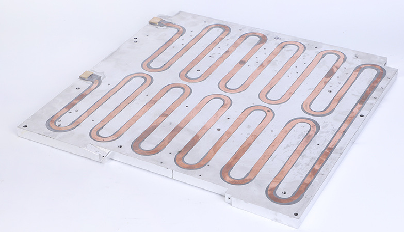
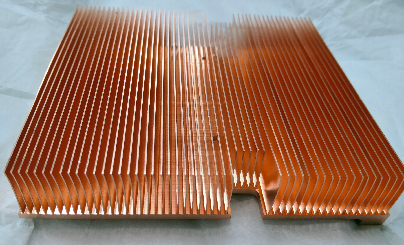
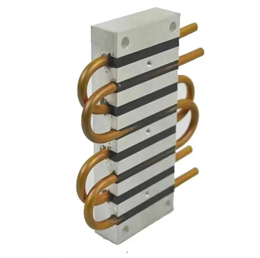
Figure 1: Multi-loop embedded copper tube cold plate
2-The Core of Design and Manufacturing: How to Balance Performance and Reliability in a Compact Space?
In multi-loop designs, the spacing between flow channels is critical to success.
a. Thermal Bottom Line: Preventing "Thermal Short Circuits"
If the spacing between adjacent flow channels is too narrow, even with independent channels, heat can rapidly conduct through the aluminum substrate in between, significantly compromising the isolation effect. Through simulation and testing, we have established a fundamental spacing principle of ≥1.5 times the tube diameter to ensure thermal independence.
b. Structural Red Line: Upholding the "Pressure-Bearing Lifeline"
The aluminum substrate between flow channels is a weak point for withstanding internal pressure. Excessively narrow spacing can lead to insufficient rib strength, posing a risk of tearing under pressure impact. Through mechanical stress simulation, we ensure that the stress between flow channels remains well below the material's yield limit under all operating conditions, fundamentally eliminating the risk of "plate rupture."

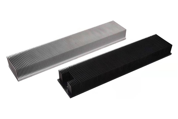
Figure 2: Embedded copper tube cold plate
c. Process Limits: Ensuring "Precision Manufacturing"
Narrow spacing poses a significant challenge for milling cutters. Based on extensive manufacturing experience, we correlate spacing with cutter diameter to ensure efficient machining while achieving smooth and flat channel walls. This lays the foundation for the subsequent tight nesting of copper tubes and low thermal resistance bonding.
3- Key Engineering Implementation Considerations
A successful multi-loop design requires attention to the following key aspects:
a. Collaborative Design
It is recommended to integrate thermal and mechanical design from the conceptual stage, taking into account flow channel layout, structural strength, and process capabilities to avoid subsequent design changes.
b. Process Control
• Utilize high-precision CNC milling for channels to ensure slot width tolerance and surface quality.
• Employ mandrel bending technology for copper tubes to maintain post-bending通畅性 and uniform wall thickness.
• Implement reliable nesting and fixation processes to prevent copper tube displacement under vibration conditions.
c. Verification Testing
A comprehensive testing system includes:
• 100% air tightness testing
• Flow rate–pressure drop characteristic testing
• Thermal resistance performance verification
• Burst pressure testing
In summary, multi-loop copper tube embedded cold plates are a powerful solution for addressing complex multi-heat source cooling challenges. The key to success lies in a deep understanding of their design logic and finding the optimal balance between performance and reliability.
We will regularly update you on technologies and information related to thermal design and lightweighting, sharing them for your reference. Thank you for your attention to Walmate.
1-Copper Tube Pre-treatment (Bending and Flattening)
Objective: To shape straight round copper tubes into flattened forms that exactly match the designed flow paths.
a. Material Selection: Why Oxygen-Free Copper?
Oxygen-free copper (C1220) has a purity of up to 99.9% and is free of grain boundary oxides, giving it excellent ductility, making it as malleable as dough. It is less prone to cracking or micro-cracking during bending and flattening, ensuring subsequent reliability.
b. Bending Radius: The Safety Bottom Line
The minimum bending radius must be ≥ 1.5 times the tube diameter—this is an iron rule. If this value is exceeded, the outer wall of the copper tube will be over-stretched, leading to thinning or even rupture. Using a mandrel bending machine is key to preventing wrinkling on the inner side.
c. Flattening: A Precise "Slimming" Process
Flattening is not simply about crushing the tube; it involves controlled plastic deformation through precision molds. The height of the flow channel after flattening must not be less than 30% of the original inner diameter. The core goal is to ensure uniform wall thickness after flattening, avoiding local dead folds or excessive thinning, as such defects would become potential leakage points in the future.

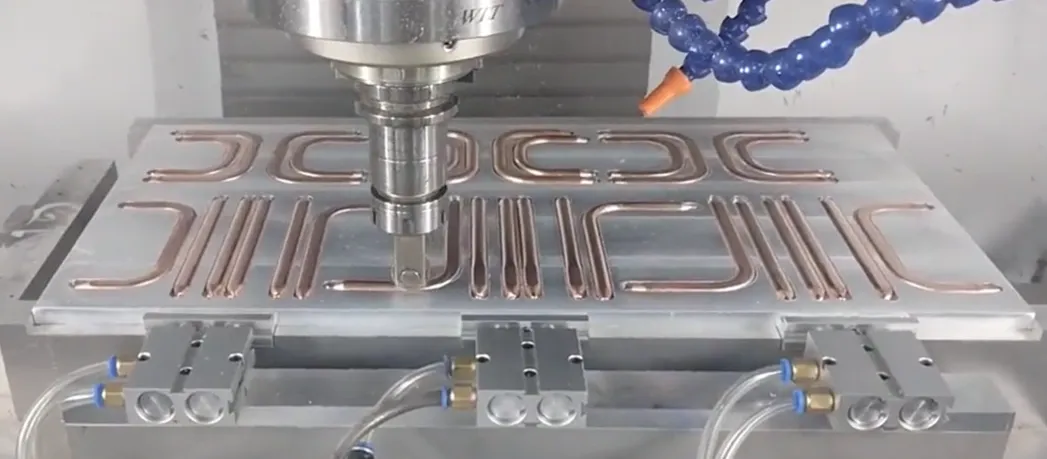
Figure 1: Heat Pipe Bending
d. Process Decision: Bend First or Flatten First?
It must be "bend first, then flatten." Bending round tubes is a mature and controllable process. If flattened first, the flattened tube can hardly undergo small-radius, high-quality bending, and the inner wall of the flow channel would be severely deformed, causing a sharp increase in flow resistance.
2-Substrate Processing (Precision Groove Milling)
Objective: To machine precisely dimensioned "tracks" on the aluminum substrate for embedding the copper tubes.

Figure 2: Embedded Copper Tube
a. Groove Width Design: Interference Fit
The groove width must be designed slightly smaller than the width of the flattened copper tube (typically by 0.05-0.1 mm) to form an "interference fit." This utilizes frictional force to tightly "grip" the copper tube, which is the foundation for initial fixation and reducing contact thermal resistance.
b. Groove Depth Control: Skiving Allowance
The groove depth determines the height by which the copper tube protrudes above the substrate surface after embedding. This height constitutes the machining allowance for the subsequent skiving process. The consistency of the groove depth directly affects the uniformity of the final remaining wall thickness of the copper tube.
c. Tooling and "Tool Chatter"
When milling narrow and deep grooves, an excessively large length-to-diameter ratio of the milling cutter can easily cause "chatter." This leads to rough groove walls and dimensional inaccuracies. Therefore, the flow channel spacing cannot be too small; sufficient space must be reserved for tool strength and rigidity.
d. Cleanliness: The Invisible Quality Factor
After groove milling, aluminum chips and oil stains must be 100% removed. Any residue will form a thermal barrier between the copper tube and the aluminum substrate, significantly increasing the contact thermal resistance and causing a substantial degradation in thermal performance.
3-Nesting and Fixation
Objective: To precisely embed the formed copper tube into the substrate groove and form a stable bond.
a. Interference Fit: The Primary Fixation Force
Relying on precise dimensional design, an external force from a press is used to "squeeze" the copper tube into the slightly narrower groove. The elastic restoring force of the material itself generates a significant normal pressure, which is the primary source of the fixation force.

Figure 3: Heat Pipe Securing
b. Auxiliary Fixation: Preventing the "Seesaw Effect"
Relying solely on the interference fit, the ends of the copper tube may lift under thermal stress. Auxiliary fixation is required: micro-spot welding (high strength, requires thermal control) or high thermal conductivity epoxy resin (low stress, but has aging risks).
c. The Enemy of Interface Thermal Resistance
Air between the copper tube and the aluminum groove is a poor conductor of heat and is the main source of interface thermal resistance. High thermal conductivity paste or welding can fill the microscopic gaps, replacing the air and significantly reducing the thermal resistance.
d. Galvanic Corrosion Warning
Aluminum and copper can form a galvanic cell in the presence of an electrolyte, where aluminum, acting as the anode, will corrode. It is crucial to ensure the cooling system's integrity and use deionized water/anti-corrosion coolant to eliminate the corrosion path at the system level.
4-Surface Finishing (Skiving vs. Deep Burial)
Objective: To form the final cooling surface, which can be used for mounting chips, characterized by high flatness and low thermal resistance.

copper tubed cold plate from Walmate
a. Skiving Process: The Performance King
This process uses ultra-hard cutting tools to simultaneously cut both copper and aluminum, creating a perfectly co-planar and flush surface. This allows the heat source to achieve direct, large-area contact with the highly thermally conductive copper tube, resulting in the lowest possible thermal resistance.
b. Deep Buried Tube Process: The Reliability Guardian
This process involves embedding round copper tubes and filling the gaps with high thermal conductivity epoxy resin. The copper tubes retain their circular shape, offering greater pressure-bearing capacity. The filler material provides additional protection and stress buffering, leading to higher reliability, although the thermal resistance is slightly higher than that achieved by skiving.
c. Final Wall Thickness: The Lifeline
The core control objective of the skiving process is the final remaining wall thickness of the copper tube. A balance must be struck between performance (requiring thin walls) and reliability/prevention of cutting through (requiring thick walls). This thickness is typically controlled within the golden range of 0.15-0.3 mm.
d. Flatness: The Guarantee of Contact
Regardless of the process used, the flatness of the mounting surface (typically required to be <0.1 mm) is a mandatory specification. Micron-level variations must be filled with thermal grease. Poor flatness will lead to a sharp increase in contact thermal resistance, resulting in cooling failure.
We will regularly update you on technologies and information related to thermal design and lightweighting, sharing them for your reference. Thank you for your attention to Walmate.

To enhance the range and capacity of electric vehicles, Power Battery Packs are transitioning from single-layer layouts to Multi-layer Stacking Structures. This shift significantly improves Energy Density, while also introducing entirely new structural challenges. This article will explore three aspects: core challenges, mainstream solutions, and future technological directions.
1-Core Challenges: Mechanical Challenges of Multi-layer Stacking
Expanding Battery Packs from a single layer to Multiple Layers is far from simple stacking. It reshapes the internal mechanical environment and external Load Paths, presenting four core challenges:
a.Vertical Load Surge and Material Creep Risk
・In Multi-layer Structures, the weight of Cells, Modules, and Structural Components accumulates layer by layer. The Static Compressive Load borne by the bottom layer is significantly higher than that of the top layer.
・This sustained High-Stress environment poses severe tests to the Long-Term Performance of materials, particularly Anti-Creep Performance (the slow Plastic Deformation of materials under Constant Stress over time).
・If Interlayer Supports or Cell Fixation Components undergo Creep, it may lead to Preload Relaxation, affecting Cell Cycle Life and Interface Contact Stability. Therefore, identifying materials that combine Lightweight properties with excellent Anti-Creep Characteristics is crucial.
b.Expansion ForceStacking Effect and Structural Stability
・Lithium-Ion Batteries experience a "Breathing Effect" during Charging and Discharging due to Volume Changes in Electrode Materials, leading to Cell Expansion. In Multi-layer Stacking Structures, Expansion Forces accumulate layer by layer, causing the bottom-layer Modules to withstand enormous pressure.
・This Cyclic Stress can easily trigger Casing Bulging, Seal Failure, Structural Component Compression, Cell Short Circuits, and accelerated Battery Performance Degradation. Effective control requires Built-in Sensors for Real-Time Monitoring combined with Digital Simulation to guide Structural Optimization Design.
c.Core Contradiction Between Space Utilization and Energy Density
・Addressing Gravity and Expansion Forces requires Reinforced Structures (such as adding Crossbeams or thickening Plates), but this occupies valuable space and increases weight, conflicting with the core goals of improving Volumetric Energy Density and Gravimetric Energy Density.
・The solution lies in Structural Optimization and the application of Efficient Materials, driving the transition of Battery Packs towards Multi-Material Hybrid Designs.
d.Collision LoadTransfer Path and Safety Redundancy Upgrade
・The Increased Height of Battery Packs intensifies Mechanical Loads during Side Impacts or Bottom Impacts; the Heightened Structure amplifies the Lever Effect, placing higher demands on Connection Point Strength and the Battery Pack's Own Stiffness.
・The use of Impact-Resistant Materials and Integrated Design is necessary to optimize Force Transfer and Energy Absorption, ensuring Cell Safety under Extreme Conditions, thereby promoting the development of Cell-to-Body Integration (CTC) technology, making the Battery Pack an integral part of the Vehicle Body Structure.
2- Comparative Analysis of Mainstream Structural Solutions
To address these challenges, the industry has explored various innovative solutions:
a.One-Piece Die-Cast Tray
・Advantages: High Integration, reduced Part Count, improved Overall Stiffness, Consistency, and Sealing. The Process supports Complex Geometries, facilitating the integration of Cooling, Reinforcing Ribs, and Mounting Points. The Monolithic Structure helps manage Complex Stresses.
・Challenges: Integral Die-Casting of Multi-Layer Frames imposes extremely high demands on Equipment, Molds, and Processes, making it costly. Post-Collision Repair is difficult or impossible. The Monolithic Rigid Structure may lack the Flexibility to manage Differential Expansion Forces between Layers.
b.Multi-Level Frame Modular
・Advantages: Flexible Design and Manufacturing, facilitating Production, Maintenance, and Replacement. Naturally suited for Multi-Material Hybrid Designs, allowing optimization of Performance and Cost for different Levels. Drawing on the "Quasi-Isotropic Lamination" concept of Composite Materials to optimize Overall Mechanical Response and disperse Stress.
・Challenges: Numerous Components and Connectors, Complex Assembly, Accumulated Tolerances affecting Precision and Preload. Numerous Connection Interfaces (Bolts, Rivets) are Potential Failure Points and add weight.
c.Hybrid Material Sandwich Structure
・Advantages: Excellent Lightweight Efficiency and extremely high Specific Stiffness (High-Strength Panels + Lightweight Core Materials such as Foam/Aluminum Honeycomb). Strong Bending Resistance, with Core Materials offering both Thermal Insulation and Energy Absorption Characteristics, enhancing Thermal Safety and Collision Safety. Aligns with the trend of Multi-Functional Integration.
・Challenges: Complex Manufacturing Process and high cost. The Interfacial Bond Strength and Long-Term Durability between Panels and Core Materials are critical. Core Materials must possess excellent Compressive Creep Resistance.
d.Bionic Honeycomb Structure
・Advantages: Theoretically an ideal Bionic Design (mimicking the HexagonalHoneycomb) for achieving Ultimate Lightweight, High Stiffness, and Compressive Strength. Provides Uniform Support with strong Impact Energy Absorption Capability.
・Challenges: Extremely complex Manufacturing and high cost, with significant Integration Difficulty with Cooling Systems etc. Currently primarily in the Frontier Research stage, requiring more time for large-scale Commercial Application.
3- Key Technological Breakthrough Directions
Future key breakthroughs in solving the Design Challenges of Multi-layer Stacking lie in:
a.Material and Process Innovation for Lightweight and Stiffness Balance
・Materials: Continuous optimization of CFRP, Aluminum Alloys, Magnesium Alloys; development of new Multifunctional Polymers and Composite Materials combining Low Creep, High Insulation, Good Thermal Conductivity, and Easy Processability.
・Processes: Development of Advanced Connection Technologies (Resistance Spot Welding, Laser Welding, Ultrasonic Welding) to achieve reliable, lightweight Multi-Material Connections.
b. Adaptive Management of Expansion Forces
Shifting the approach from "Rigid Resistance" to "Flexible Adaptation", creating Dynamic Response Systems to keep Cells in the Optimal Stress Environment throughout their Lifecycle.

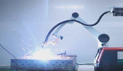
Figure 1: Robotic laser welding of battery trays
c.Interlayer Connection and Integration Revolution
・Connection Technologies: Evolution from BoltMechanical Connections to Structural AdhesiveBonding and Advanced Welding for more uniform Stress Distribution, Good Sealing, and Fatigue Resistance.
・Ultimate Integration: CTC/CTB (Cell-to-Chassis/Body) is an important future direction for Battery PackIntegration. By eliminating Independent Housings and directly integrating Cells or Modules into the Chassis, the Multi-layer Stacking itself becomes a Vehicle Body Structural Component (such as Crossbeams or Floors), fundamentally solving Space Constraints and maximizing Battery Structural Functionality. Achieving this technology requires Deep Collaboration across multiple fields including Batteries, Structures, Thermal Management, and Safety, representing the Ultimate Form of the "Structure as Function" concept.

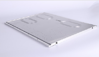
Figure 2: EV Battery tray
Multi-layer Stacking is an inevitable choice for increasing BatteryEnergy Density, but it also brings enormous challenges in Structure, Expansion Forces, and Safety. The solution lies in Material Innovation, Bionic Structural Optimization, and Intelligent Management of Expansion Forces. Ultimately, Battery Packs will Deeply Integrate with Vehicle Bodies, becoming an integrated "Energy Chassis".
We will regularly update you on technologies and information related to thermal design and lightweighting, sharing them for your reference. Thank you for your attention to Walmate.
Two Core Challenges of Electric Heavy-Duty Trucks: In-Depth Analysis of Battery Layout and Stacking Technology
When a fully loaded electric heavy-duty truck travels on highways, the secret to its hundreds of kilometers of range lies within its chassis and battery compartment. As the wave of heavy-duty truck electrification sweeps the global logistics industry, the layout and stacking technology of battery systems have become critical to market success.

Figure 1: Liquid Cooling Solution for Electric Heavy-Duty Truck Batteries
1-Battery Layout: How Three Solutions Reshape Electric Heavy-Duty Trucks?
a. Back-Mounted Layout: Agile Choice for Short-Distance Transport
· Scenario: Short-haul operations in enclosed areas like ports, mines, and steel plants.
· Core Advantage: Rapid battery swapping (specific times require validation), improving vehicle utilization.
· Limitations: Battery capacity constraints (<350 kWh industry standard), high center of gravity affecting stability.
· Space Trade-off: Occupies cargo or cabin space, reducing load capacity.
b. Chassis-Mounted Layout: Endurance King for Long-Haul Transport
· Capacity Breakthrough: Battery capacity exceeds 500 kWh (e.g., disclosed 513 kWh solutions).
· Space Efficiency: Maximizes chassis space, avoiding cargo encroachment.
· Safety: Ultra-low center of gravity enhances high-speed stability.
· Technical Barriers: Chassis integration demands higher protection and thermal management.
c. Bottom-Side-Mounted Layout: Efficiency Engine for Battery Swap Networks
· Innovation: Lateral battery swapping boosts operational efficiency.
· Space Balance: Preserves full cargo space, with range between back and chassis layouts.
· Safety Focus: Requires reinforced side-impact protection structures.
2-Stacking Technology: Efficient Integration Solutions for Truck Battery Packs
Multilayer stacking is key to improving energy density:

Figure 2: Stacked Liquid Cooling Integration Box for Heavy-Duty Trucks
a. Frameless Integrated Stacking:
· Direct cell stacking reduces structural components.
· Eliminates modules/frames, enabling "Seamless Z-Stacking".
· Significantly boosts system energy density.
· Supports ultra-fast charging (performance requires validation).
b. Module-to-Chassis Integration (e.g., MTB/CTC):
· MTB: Modules directly connect to the frame, improving volume utilization.
· Qilin Battery(CTP 3.0): 72% volume utilization, 255 Wh/kg energy density.
· CTC: Cells integrate into the chassis, reducing weight by 10%.
c. Cell Form Innovation (e.g., Blade Battery):
· Flat cells tightly arranged, increasing volume utilization (>50% per BYD data).
· Breaks LFP energy density bottlenecks.
3-Core Technical Challenges
Challenge 1: Structural Safety
· Extreme Conditions: Side-pole collisions threaten side-mounted layouts.
· Solutions: High-strength aluminum alloy housings + buffers; FEA collision simulation; super-national mechanical impact tests.
Challenge 2: Thermal Management
· Critical Issue: Temperature differential control within packs is vital.
· Innovations: Lateral liquid cooling(<3°C differential); direct refrigerant cooling; MPC dynamic control.
Challenge 3: Vibration Fatigue
· Hidden Risk: Road vibration causes structural damage.
· Strategies: Z-stacking optimizes stress distribution; road spectrum vibration testing; high-damping materials.
4-Current Development Trends
· Chassis-mounted layouts dominate medium/long-haul: High range (>500 kWh) and low center of gravity are preferred.
· CTC integration fuses batteries with chassis, improving space utilization and rigidity.
· AI-driven thermal management enables precise temperature control (<5°C differential), extending battery life.
· Semi-solid-state batteries accelerate commercialization, focusing on safety and energy density.
We will regularly update you on technologies and information related to thermal design and lightweighting, sharing them for your reference. Thank you for your attention to Walmate.
The wave of electric heavy-duty trucks is sweeping across the global logistics and transportation industry, injecting strong momentum into the "dual-carbon" goals. However, with the soaring demand for extended range, battery systems with single-pack capacities exceeding 500kWh or even approaching 1000kWh have become commonplace. This is akin to equipping vehicles with a mobile "energy fortress," but the potential thermal safety risks have also reached unprecedented levels. When the three extreme safety indicators—"ultra-large capacity," "ultra-fast thermal propagation" (<2 minutes), and "ultra-high collision resistance" (>1500kJ)—converge, the industry faces a severe technological gap. This article analyzes these challenges and explores systematic solutions to build a dedicated safety defense line for electric heavy-duty trucks.

Figure 1: Short-Blade Three-Layer Stacking Solution
1-The 500kWh+ Era: Opportunities and Safety Challenges Coexist
a. Capacity Leap Has Become the Norm
To meet the demands of heavy-load, long-distance transportation, the battery capacity of electric heavy-duty trucks has rapidly increased from 200-300kWh to 600kWh+. Industry leaders have rolled out solutions ranging from 500kWh and 600kWh to even 1000kWh, marking the official arrival of the ultra-large-capacity era.
b. The Maturity of LFP (Lithium Iron Phosphate) Battery Technology
LFP batteries have become a major driver due to their advantages in safety and cycle life, making them the mainstream choice for heavy-duty trucks.
2-The "Three Major Challenges" Under Extreme Safety Demands
a. Thermal Propagation Limit Control (<2 Minutes)
· Core Objective: Safety designs must delay or block thermal propagation to create a time window for evacuation and rescue (e.g., the 5-minute early warning requirement under China's GB 38031-2020 standard).
· Harsh Reality: In high-density battery packs exceeding 500kWh, the massive energy released by a single cell during thermal runaway can easily trigger a catastrophic chain reaction. Test data shows extremely rapid thermal propagation: in some cases, it takes only 22 seconds to engulf the entire pack, 5 seconds to ignite adjacent modules, and as little as 44 seconds for inter-module propagation.
· Core Difficulty & Gap: How to effectively ensure inter-module thermal propagation is controlled beyond 2 minutes? Currently, no commercial heavy-duty truck system has publicly claimed or verified compliance with this stringent requirement.
b. Structural Collision Resistance Barrier (>1500kJ)
· Core Requirement: The collision energy of a fully loaded heavy-duty truck far exceeds that of passenger vehicles, easily surpassing 1500kJ. As a structural component of the chassis, the battery pack must possess ultra-high strength to remain intact post-collision, preventing internal cell damage that could lead to thermal runaway.
· Harsh Reality: Current domestic and international standards (e.g., GB/T 31467.3-2015, UNECE R100) lack clear or sufficient thresholds for collision energy testing of heavy-duty truck battery packs. Publicly available certification data for systems passing 1500kJ-level collision tests is extremely scarce. Although higher-energy simulations exist (e.g.,2500kJ), full-system validation remains a significant challenge.
· Core Difficulty & Gap: The absence of clear high-energy collision protection standards and thoroughly validated solutions.
c. Secondary Disaster Chain Risks (Cargo Explosion & Road Paralysis)
· Cargo Explosion Risk: High-temperature flames from battery thermal runaway can easily ignite cargo (especially hazardous materials), forming a disaster chain: "battery runaway → cargo fire → explosion."
· Road Paralysis Risk: Lithium battery fires are difficult to extinguish (requiring large volumes of continuous cooling water) and prone to reignition. A multi-ton heavy-duty truck catching fire on a highway or in a tunnel complicates rescue efforts (high-voltage power cutoff, toxic gas prevention) and takes an extended time (up to several hours, with potential impacts lasting 24 hours), severely disrupting traffic and causing significant societal repercussions.
· Core Difficulty & Gap: The lack of targeted quantitative road clearance time standards and efficient emergency response systems.
3-Building the Defense Line: Thermal Event Early Warning System Design – Four-Layer Protection Net

4-Thermal Management Supporting Solutions: Empowering the Early Warning System
· Liquid Cooling System: Integrated high-efficiency liquid cooling plates eliminate localized hotspots, maintaining a temperature difference of <3°C between cells.
· Modular Design: Independently detachable module structures enable quick replacement of faulty units.
· Intelligent Monitoring Platform: Cloud-based real-time battery health analysis with automatic early warning alerts sent to maintenance teams.
We will regularly update you on technologies and information related to thermal design and lightweighting, sharing them for your reference. Thank you for your attention to Walmate.

In the new energy heavy truck market, "battery stacking" has become a key term: mainstream models now exceed 370kWh in battery capacity, with 600kWh+ models frequently debuting. This is not just a leap in technical specifications but also the industry's declaration of a full-scale assault on the line-haul logistics market—by enhancing single-charge range, addressing the core user pain point of "range anxiety," and optimizing total cost of ownership (TCO). This article will dissect the business logic and technological breakthroughs behind this trend.
1-Business Logic: Why Must We "Stack Batteries"?
a. Scenario-Driven Necessity
·Closed Scenarios (Short-Distance, High-Frequency): Ports, mines, and similar settings rely on battery-swapping models (3-5 minute recharge), where 280kWh batteries suffice.
·Line-Haul Logistics (Long-Distance Transport): Accounts for 70% of freight volume, requiring a single-charge range of 500+ km. 600kWh+ batteries serve as the "gateway" to this market.
b. The Economics of TCO

Key Conclusion: When daily mileage exceeds 300 km, the TCO of battery-swap heavy trucks begins to outperform diesel trucks.
b. Model Innovation: Resolving Cost Challenges
·Battery-as-a-Service (BaaS): Users purchase the "bare vehicle" with battery leased monthly (¥5,000–9,000), reducing upfront costs by 30%.
·Battery Swap Services: Service fee of ¥0.2–0.5 per kWh, with total energy costs around ¥2.73/km (close to diesel trucks at ¥2.8/km).
·Commercial Validation: A swap station serving 50 vehicles/day can shorten the payback period to 5 years (IRR of 13.1%).
2-Technological Breakthroughs: How to Balance Range and Weight?
a. Spatial Compromise: Chassis for Space
·To prevent batteries from encroaching cargo space, the industry is optimizing battery layout. For example, integrating batteries into the chassis (replacing traditional rear-mounted designs) frees up cargo volume, lowers the center of gravity, and may improve energy efficiency.
·Trade-off: Reduced ground clearance and compromised chassis modularity.
b. Material Science Compromise: Energy Density for Weight
·The key to weight reduction lies in improving battery energy density (more energy stored per unit weight). Higher density enables lighter batteries or extended range at the same weight.
·Core Innovation: Battery materials (e.g., high-nickel cathodes, silicon-carbon anodes).
·Trade-off: Higher energy density often comes with safety risks, shorter lifespan, increased costs, and reduced fast-charging capability—requiring difficult multi-parameter balancing.
c. Business Model Compromise: Network Over Single-Vehicle Pressure
·The battery-swap model shifts the "infinite range" burden from individual vehicles to the swap network. By deploying dense swap stations along routes, trucks only need enough charge to reach the next station, eliminating oversized batteries.
·Outcome: Reduces extreme battery capacity demands, making onboard battery loads more "rational."
d. Residual Value Management: The Core Barrier for BaaS
Battery banks must develop full lifecycle capabilities: State-of-Health (SOH) monitoring, cascading reuse, and recycling systems.

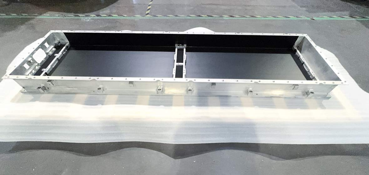
Figure 1: Heavy-duty truck battery pack enclosure
3-Future Trends: From "Battery Stacking" to "Efficient Energy Loading"
a. Technology Evolution: Solid-state batteries will break energy density barriers, rebalancing weight and range.
b. Charging Infrastructure: Standardized heavy-truck swapping protocols and grid synergy (e.g., peak shaving) are critical for scale.
c. Multi-Path Competition: Hydrogen-powered heavy trucks retain substitution potential in long-haul, heavy-load segments.
Conclusion: Phased Strategy, Long-term Evolution
"Battery stacking" is an inevitable choice for electric heavy trucks to conquer line-haul logistics, reflecting a dynamic balance between commercial needs and technical realities. As battery technology advances and business models mature, the industry will shift from a "capacity race" to an "efficiency race." Currently, it is driving China's new energy heavy trucks to complete the critical leap from "niche" to "mainstream."
We will regularly update you on technologies and information related to thermal design and lightweighting, sharing them for your reference. Thank you for your attention to Walmate.

Core of Thermal Management for Heavy-Duty Truck Battery Packs: Dual Breakthroughs in Lightweight Materials and Manufacturing Processes
Heavy-duty trucks (HDTs), as the core force in road logistics, have made the safety, reliability, and cost-effectiveness of their battery systems a key technological focus. The battery tray, as the critical structural component that carries, protects, and manages battery modules, is now facing unprecedented extreme challenges.

Figure 1: Battery tray for electric heavy-duty trucks
1-Extreme Challenges for Heavy Duty EV Battery Tray
a. Stringent Mechanical Durability Requirements: Vibration, Impact, and Million-Kilometer Service Life
Heavy-duty trucks are designed with a service life of ≥1.5 million kilometers, 10 times longer than that of passenger vehicles. The battery tray must continuously withstand the following three types of extreme mechanical loads throughout its entire lifecycle:
·High-frequency random vibrations: When fully loaded and driving on unpaved, construction, or uneven roads, the chassis generates random vibrations across a wide frequency band (5 Hz–2 kHz). These vibrations not only test the fatigue limit of the tray's main frame but also induce microcracks in stress concentration zones such as welds, bolt holes, and flanges, becoming potential failure initiation points.

·High-g transient impact: Deep potholes, emergency braking, or handling drops can generate impact accelerations exceeding 50 g within milliseconds. The tray must instantaneously absorb/dissipate energy to prevent cell displacement, short circuits, or casing rupture.
·Cumulative fatigue damage: A million-kilometer service life means hundreds of millions of vibration cycles. Under alternating stress, aluminum alloys are prone to fatigue crack initiation and propagation, eventually leading to structural fracture. The core design task is to delay crack initiation until after the vehicle's retirement through topology optimization, local reinforcement, hybrid material integration, and process control.
b. Complex Thermal Management and Thermal Cycling Challenges
Due to their ultra-high capacity (hundreds of kWh) and high-power charging/discharging, heavy-duty truck battery packs generate massive heat. They also operate across arctic to tropical environments, facing extreme temperature differentials.
·Wide-temperature-range control: The tray and thermal management system (TMS) must precisely maintain cell temperatures within the optimal 25–40°C range under ambient temperatures ranging from -40°C to +85°C, with <5°C temperature variation between individual cells.
·High-stress thermal cycling: In accelerated aging tests, the system must endure thousands of -40°C ↔ +85°C thermal shock cycles (ramp rate: 5–15°C/min, dwell time: 5–15 minutes). This process causes repeated thermal expansion/contraction at material interfaces (aluminum alloy/sealant/plastic components), posing severe challenges to the reliability of welded/adhesive joints in integrated cooling channels.
2-Mainstream Material Solutions and Multi-Functional Integration Technologies
To address these challenges, the industry has developed a technology roadmap based on high-strength aluminum alloys, evolving toward highly integrated multi-functional designs.
a. Core Material Selection: The Dominance of 6xxx-Series Aluminum Alloys
In competition with steel, magnesium alloys, and composites, 6xxx-series (Al-Mg-Si) aluminum alloys have become the mainstream material for heavy-duty truck battery trays due to their excellent comprehensive performance, mature processing techniques, and high cost-effectiveness.
Key Alloy Grades and Properties:
·6061-T6: The most widely used grade, renowned for its outstanding strength, good weldability, and corrosion resistance.
·6005A-T6 and 6063-T6: Supplementary options, also offering good extrudability, suitable for components with slightly lower strength requirements.

b. Paradigm Shift in Design Philosophy: Thermal Management and Structural Health Monitoring
The design philosophy of modern heavy-duty truck battery trays has undergone a fundamental transformation—evolving from a purely mechanical "load-bearing structure" to a highly integrated "intelligent thermal regulation platform." This shift is primarily manifested in two key technological directions:
·Integrated Thermal Management (Mature Application)
Currently the most technologically mature and widely adopted approach, its core concept involves embedding cooling functionality directly into the tray's structural design to achieve compact and efficient thermal regulation.
·Structural Health Monitoring (SHM) Exploration (Early Stage)
This emerging technology aims to preemptively detect potential structural damage (e.g., cracks, deformations) during long-term service. However, it remains in the validation and laboratory research phase, lacking large-scale commercial deployment cases or sufficient long-term operational reliability data.
3-Analysis of Core Manufacturing Process Routes
The manufacturing processes for heavy-duty truck battery trays directly determine their cost, performance, and production efficiency. The mainstream approach combines aluminum extrusion and friction stir welding (FSW), optimally balancing performance requirements with small-to-medium batch production models.
a. Aluminum Extrusion
This process shapes aluminum billets into elongated structural components (e.g., crossbeams, longitudinal beams) via dies. As the cornerstone technology for battery trays, it offers:
·Advantages: Low mold costs, short development cycles, and adaptability to large, non-standardized parts in small batches.
·Limitations: Requires cutting, machining, and multi-step welding assembly, resulting in low automation, slower cycle times, and inferior efficiency compared to integrated die casting.
b. Friction Stir Welding (FSW)
A solid-state joining technology, FSW generates heat via a rotating tool to achieve high-strength aluminum welds, making it the premier choice for load-bearing/sealed joints:
·Performance: Weld strength reaches 80–90% of the base material, with no porosity/cracking defects. Minimal thermal distortion ensures IP67+ sealing and eco-friendliness.
·Constraint: Limited to flat/simple-curved weld geometries.
Aluminum alloy heavy-duty truck battery trays have transcended their role as high-strength lightweight structures to become multifunctional integrated platforms. However, proliferating functionalities introduce challenges like multi-physics coupling failures, process complexity, and reliability risks. Future breakthroughs will hinge on material-process-system co-innovation, leveraging adaptive interfaces and digital twin technologies to enable the safe and sustainable evolution of intelligent trays.
We will regularly update you on technologies and information related to thermal design and lightweighting, sharing them for your reference. Thank you for your attention to Walmate.

5 Optimization Guidelines for Energy Storage Liquid Cooling Plate Design Amid the 500Ah+ Large Battery Cell Wave
Cost-Driven Large Cell Revolution and Cooling Challenges:The energy storage industry is undergoing a profound transformation driven by "cost reduction and efficiency enhancement" – the rapid rise of the large cell technology roadmap. 300Ah+ cells are becoming standard, while 500Ah and even higher capacity cells are accelerating their deployment. While this revolution enhances system energy density and reduces per-watt-hour costs, it also presents severe challenges: a dramatic increase in individual cell mass, a surge in module/pack (battery pack) overall weight, multiplying the load-bearing pressure on bottom support structures; larger heat generation power and longer internal heat transfer paths impose extreme demands on the efficiency and uniformity of the thermal management system. As the core of pack thermal management, liquid cold plates face the brunt of the upgrade pressure.

Traditional "thin-plate covering" cold plate designs are no longer sustainable. Under constraints of limited space and stringent cost control, cold plates must transcend their single function of heat dissipation and evolve towards a trinity of "structural-functional integration, ultimate heat dissipation efficiency, and system lightweighting." This article will delve into this advanced design pathway.
1-Structural-Functional Integration: The "Load-Bearing Revolution" of Cold Plates
As cell mass significantly increases, the loads borne by the enclosure baseplate and the cold plate surge dramatically. Designing the cold plate as a load-bearing structural component is the key breakthrough point for resolving the conflicts between weight, cost, and space.
a.Becoming the Enclosure's "Skeleton": Integrated Load-Bearing Baseplate
Design Concept:The cold plate no longer attaches to the enclosure baseplate; instead, it becomes the primary load-bearing structure of the enclosure itself.
Core Advantages: Significantly reduces traditional baseplates and mounting brackets, markedly lowering system weight and material costs, and simplifying the assembly process.
Technical Requirements: Must demonstrate extremely high bending, compression, and impact resistance stiffness and strength.
b. Embedding "Steel Reinforcement": Topology Optimization and Reinforcement Structures
Mechanics-Led Design: Utilize CAE simulation for topology optimization, integrating stiffening ribs, etc., within non-critical heat dissipation areas of the cold plate (e.g.flow channel gaps, edges).

Efficient Material Utilization: Optimized design ensures material is distributed along critical stress paths, removing redundant material, achieving lightweighting while guaranteeing load-bearing capacity.
c.Module-Level Load-Bearing Platform: Consolidating Components
Large-scale, high-strength cold plates can directly serve as the mounting baseplate and load-bearing skeleton for modules. Cells or modules are fixed directly onto them, eliminating the need for additional support frames, further streamlining the structure and improving volumetric efficiency.
2-Significant improvement in heat dissipation performance: the art of balancing efficiency and equation
The core pain points of large battery cells are the difficulty in dissipating heat in the central area and controlling the overall temperature difference. The design of liquid cooled plates requires innovation from multiple dimensions including flow channels, interfaces, and materials.
a. Flow channel design: from "simple pipeline" to "intelligent blood vessel"
·Precise diversion and enhanced turbulence: Adopting a tree branch flow channel, serpentine+turbulence column/fin composite structure, to increase flow and disturbance in the high heat zone of the cell center. Avoid the "fast edge cooling and slow center cooling" caused by the straight path with large drift diameter.
·Variable cross-section and zone cooling: Based on the heat generation in different areas of the battery cell (such as center>edge), design gradient cross-section flow channels or independently controllable zone circuits to achieve precise and on-demand heat distribution, with temperature difference control up to ± 2 ℃.
·Biomimetic and Topology Optimization of Flow Channels: Utilizing CFD and topology optimization techniques to generate an efficient and low resistance "natural growth" flow channel network, maximizing heat transfer area and efficiency, and reducing pump power loss.
b. Breaking through interface thermal resistance: making "contact" tighter
·High performance interface material (TIM): research and develop high thermal conductivity (>5W/mK), low thermal resistance, long-term stable thermal conductivity gasket/gel/phase change material, and take into account insulation, cushioning and processability.
·Microstructure surface engineering: Processing micro grooves, array micro protrusions, or applying special coatings on the contact surface of the cold plate to increase the effective contact area, enhancing contact through capillary force, and significantly reducing interface thermal resistance (can be reduced by 30% -50%).
c. Material Upgrade: Dual Pursuit of Thermal Conductivity and Strength
Exploring higher thermal conductivity aluminum alloys (such as high thermal conductivity 6-series and specific 7-series alloys) or aluminum based composite materials (AMCs) while ensuring structural strength, to enhance basic thermal conductivity.
3-Lightweight throughout: a weight game where every gram is worth fighting for
Every gram of weight loss means reduced costs and improved transportation and installation efficiency.
Refined 'slimming' design:
a. Simulation driven thinning: Through precise CAE calculations, the maximum thinning of the cold plate wall thickness is achieved while meeting strength, stiffness, and heat dissipation requirements (such as reducing from 2.0mm to 1.5mm).
b. Hollow structure and hollow out: Design hollow cavities or perform safe hollow out treatment inside the reinforcing ribs and non critical areas.
c. Application of high-strength materials: Using higher strength aluminum alloys (such as 7xxx series) to achieve thickness reduction and weight reduction under the same performance.
4-Manufacturing process: the cornerstone supporting advanced design
The "structuring" and "complexity" of liquid cooled plates pose higher requirements for manufacturing processes.
Upgrading and integration of mainstream processes:
·Aluminum extrusion+Friction Stir Welding (FSW): advantages lie in large size and high structural strength. Advanced direction: Developing complex profile sections with integrated flow channels and reinforcing ribs; Breakthrough in ultra long and variable cross-section FSW welding technology to ensure weld strength and airtightness.
·Stamping+brazing: The advantage lies in flexible channel design and great potential for lightweight. Advanced direction: Achieving precision stamping of deeper and more complex flow channels; Improve the yield and joint reliability of large-sized and multi-parts-brazing; Integrate reinforced structures on stamped parts.
·High pressure die-casting: The potential lies in manufacturing highly integrated and extremely complex-shaped cold plates (with integrated flow channels, rib positions, and interface oneness) .Challenges such as mold cost, internal channel surface smoothness, and pore control should be overcome.
·Hybrid process innovation: Multi process combination innovation, integrating the advantages of different processes to meet more complex design requirements.
5-Reliability: the lifeline of integrated design
When the liquid cooled plate becomes the core of the structure, its reliability is related to the safety of the entire PACK.
Strengthen the dual reliability of "structure-fluid":
a. Extreme mechanical verification: It is necessary to simulate extreme working conditions through vibration, impact, compression, and drop tests that far exceed the standard.
b. Fatigue life guarantee: Conduct detailed structural fatigue and pressure cycle simulation and testing to ensure no leakage or cracking under long-term alternating loads.
c. Redundant sealing design: Key interfaces and the use of multiple sealing strategies.
d. Strict quality control: Introducing automated online testing to ensure manufacturing consistency.
The advanced path of energy storage liquid cooled plates is a vivid epitome of technological innovation driving industry cost reduction and efficiency improvement. Whoever can win the first place in the design competition of "structural functional integration" will have an advantage in the competition of the trillion dollar energy storage market. This silent 'bottom plate revolution' is quietly reshaping the future form of energy storage systems.
We will regularly update you on technologies and information related to thermal design and lightweighting, sharing them for your reference. Thank you for your attention to Walmate.
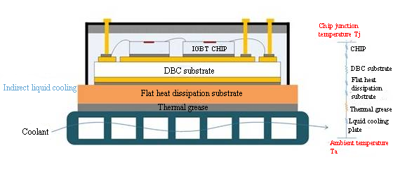
The essence of IGBT heat dissipation is the problem of heat transfer efficiency under multi-layer thermal resistors in series, among which the interface thermal resistance accounts for more than 60% and is the main optimization object.

Figure 1: IGBT thermal resistance diagram
1-The root of the problem: Where is the thermal resistance hidden?
The thermal resistance of the IGBT module is a complex multi-layer structure involving multiple material layers and heat conduction paths. The thermal resistance of the IGBT module is mainly composed of the thermal resistance (Rth) of the IGBT module, which is composed of the junction-case thermal resistance (Rth-Rjc) and the case-ambient thermal resistance (Rth-Rca) in series:
a. Junction-case thermal resistance (Rth-Rjc):
· Copper-clad ceramic board is the main bottleneck: accounting for more than 75% of Rth-Rjc, because its ceramic layer (such as Al₂O₃) has low thermal conductivity (15–35 W/m·K) and its thickness cannot be ignored.
· Other levels account for the remaining 25% of the chip thermal resistance (silicon-based thermal conductivity ≈ 150 W/m·K), solder layer thermal resistance (voids cause interface thermal resistance), and copper substrate thermal resistance (high thermal conductivity but small thickness effect). b. Shell-ambient thermal resistance (Rth-Rca):
· Interface contact thermal resistance is dominant: The thermal resistance of the thermal grease/contact surface between the substrate and the heat sink accounts for 40–60% of the total thermal resistance, and accounts for more than 60% in the traditional single-sided heat dissipation design.
· Influence of heat dissipation structure: For example, in an air-cooled heat sink, the contact thermal resistance (Rjc), thermal conductivity thermal resistance (Rch), and heat exchange thermal resistance (Rha) account for 65.9%, 5.9%, and 28.2% respectively (conventional fin structure).
2- Path to overcome thermal resistance: Coordinated optimization of materials and structures
a. Chip thinning: reducing internal thermal resistance
· Technological evolution: Thinning from 200μm PT wafer to 70μm for IGBT7, reducing thermal resistance by 60%. Thinning process (grinding/CMP/plasma etching) can release stress and improve thermal diffusion efficiency.
· Physical mechanism: The thickness is reduced from 350μm to 110μm, and the heat capacity per unit area (Cth) is reduced from 786.5 J/℃·m² to 247.2 J/℃·m², accelerating transient heat dissipation. After thinning, the resistance is reduced, the ohmic contact is enhanced, and the failure risk caused by internal stress is reduced.
b. Interface innovation: silver sintering replaces thermal conductive silicone grease
Interface material upgrade is the core of reducing contact thermal resistance:

Table 1: Comparison of thermal conductivity between silver sintering and thermal conductive silicone grease
c. Substrate upgrade: high thermal conductivity ceramics and diamond
Substrate materials are undergoing a key evolution from Al₂O₃ to AlN and then to diamond. The core goal is to significantly improve thermal conductivity to meet the heat dissipation needs of higher power density electronic devices.
· Breakthrough of AlN substrate
The thermal conductivity can reach 5–10 times that of Al₂O₃. The thermal expansion coefficient (about 4.5 ppm/K) is closer to silicon (about 2.6 ppm/K), which effectively reduces the thermal mismatch stress between silicon chips.
· Prospects of diamond substrates: Thermal conductivity exceeds 2000 W/(m·K) (80 times that of Al₂O₃), thermal expansion coefficient is 1.1 ppm/K, perfectly matching silicon chips. The thermal conductivity of diamond/aluminum composite materials reaches 613 W/(m·K) (2.6 times that of pure aluminum), and interface optimization improves bonding strength.

Table 2: Comparison of key substrate material properties
3- Challenges of overcoming thermal resistance
a. Mechanical strength bottleneck of chip thinning
Reducing the thickness from 200μm to 70μm (IGBT7) can reduce thermal resistance by 60%, but further thinning to 20μm will cause the risk of fracture. Ultra-thin chips (<50μm) are prone to microcracks due to mismatch of thermal expansion coefficient (CTE).
b. Challenge of high thermal conductivity substrate

Table 3: High thermal conductivity substrate challenges
c. Interface reliability: Multi-physics coupling challenge
· Risk of silver sintering CTE mismatch: The silver sintering layer (CTE=18.4 ppm/K) differs by 4 times from the SiC chip (CTE=4.5 ppm/K), and thermal cycling is prone to delamination.
· Interface contact pressure control: Pressure 0.1→0.5 MPa can reduce thermal resistance by 40%, but >1 MPa will squeeze out the silver layer.
When IGBT power density enters the 10kW/cm² era, heat dissipation design has leaped from "auxiliary engineering" to "system bottleneck breakthrough point". The substrate revolution from Al₂O₃ to diamond, the interface transition from silicone grease to copper sintering, and the chip slimming from 200μm to 50μm are essentially a battle against the second law of thermodynamics. Heat dissipation design is approaching the physical limit, and the triangular synergy of materials, structure and process will become the key to breaking through.
We will regularly update you on technologies and information related to thermal design and lightweighting, sharing them for your reference. Thank you for your attention to Walmate.
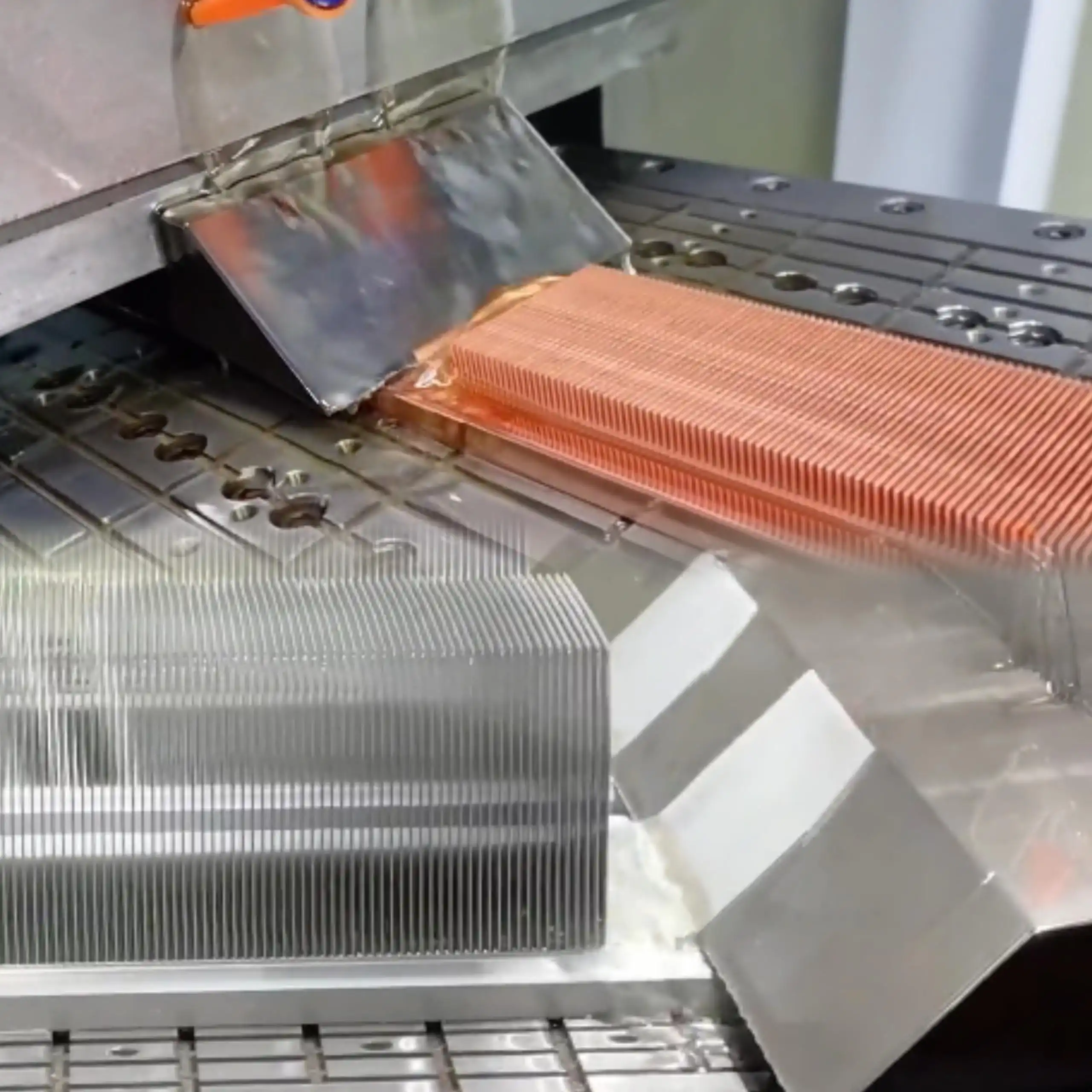
Aluminum replacing copper has become an irreversible trend in the field of Skived fin heat sinks. The core driving forces are cost, lightweight and resource security, and the performance gap is made up through process innovation (skiving technology, microchannel design). In typical applications, aluminum solutions have been widely used in high-efficiency scenarios such as data centers and new energy vehicles. However, aluminum replacing copper is not a simple material replacement, but a systematic project that requires comprehensive optimization from material selection, structural design, manufacturing process to application scenarios to achieve the best balance between cost and performance. This article will explore in depth the key technological breakthroughs and application solutions in this replacement practice.

1-Aluminum vs. Copper: Material Properties and Replacement Challenges
To scientifically evaluate the feasibility of aluminum replacing copper, we must first understand the differences in the core physical properties of the two metals in heat dissipation applications:

Table 1: Comprehensive comparison of aluminum and copper heat dissipation material properties
The performance of the heat sink depends not only on the thermal conductivity of the material, but also on the heat capacity characteristics and surface area utilization. The difference in physical properties between aluminum and copper determines the feasibility boundary of substitution:
a. The dialectical relationship between thermal conductivity and heat capacity
·Instantaneous advantage of copper: high thermal conductivity (385W/m·K), faster initial heat diffusion;
·Steady-state breakthrough of aluminum: high specific heat capacity (900J/kg·K, 2.3 times that of copper), 133% increase in heat storage capacity per unit mass, low density (2.7g/cm³, 30% of copper), 40% increase in heat dissipation area for the same volume, and long-term balance achieved through a larger surface area during the continuous heat dissipation stage.
b. Thermal matching addition
The thermal expansion coefficient of aluminum (23.1×10⁻⁶/K) is close to that of PCB substrate (13-18×10⁻⁶/K), reducing the risk of thermal stress failure.
In addition, the trend is being driven by a change in performance perspective - accepting a reduction in local thermal conductivity in exchange for system-level lightweighting, cost optimization, and improved sustainability.
2-Key breakthroughs in manufacturing process
a. Material system breakthrough: alloy composition optimization and hardness control
· Traditional pain points: Traditional aluminum materials (such as 1060 pure aluminum) have low hardness (24-38HB) and are easy to skived fin, but subsequent machining is prone to sticking to the tool; 6063 aluminum alloy has high hardness (34-42HB), which is conducive to later processing, but the skived height is limited (≤50mm).
· Breakthrough point: Through alloy composition optimization (Si 0.25%, Mg 0.41%) and melting and casting process innovation (556℃ homogenization + 430℃ extrusion/490℃ quenching), the hardness of aluminum materials is controlled in stages: maintain a low hardness of 32-39HB before skived fin (to ensure 70mm high fin processing), and strengthen to 55-64HB after skived fin (to solve the problem of sticking to the tool during machining).
·Impurity control and thermal conductivity balance: With high purity control of Fe≤0.11% and Cu≤0.02% (99.70% aluminum base), high thermal conductivity is maintained while improving machining efficiency, so that high fin aluminum radiators have both processing performance and service strength.
b. The essential difference between material hardness and cutting response: The core advantage of aluminum in achieving ultra-thin fins lies in its work hardening characteristics and cutting force requirements.
Technical analysis:
·The soft properties of copper lead to the process of skived fin: tool extrusion easily causes material accumulation at the root of the fin (forming a "curling effect")
The thin film area has severe plastic deformation (high instability rate when the thickness is <0.1mm); the degree of work hardening is weak, and the structure cannot be strengthened by deformation.

·When skiving aluminum alloy: work hardening significantly improves the stiffness of the fin (the strength of 6063 alloy is improved after cold hardening); low cutting force allows the use of more precise thin-blade tools; small elastic recovery (about 1/3 of copper) to ensure the geometric accuracy of the fin.
c. Breakthrough in structural limits and cost optimization
The design of ultra-thin fins is essentially to maximize the surface area/volume ratio, and the physical properties of aluminum are more suitable for this goal:

Table 2: Comparison of parameters of aluminum and copper skived fin heat sinks
Simple cross-section aluminum profiles (plate/groove) are used to replace complex molds, reducing mold costs by 60%. Small-batch production directly uses plate skived fin (mold-free) to adapt to customized needs.
3-Trend Essence: System Optimization Replaces Material Egoism
The core value of aluminum skived fin heat sink lies in the comprehensive optimization of the system level, rather than the replacement of a single thermal conductivity performance:
·Technical leverage: Achieve a synergistic breakthrough in lightweight and efficient heat dissipation through high-multiple fins structure, thin fin process and one-piece molding;
·Lightweight integration advantage: In emerging fields such as new energy/5G, lightweight and cost have become more critical indicators than absolute thermal conductivity, and derivative benefits have been improved.
·Full-cycle economy: The initial cost is only 45% of the copper solution, and the fan power consumption reduction brought by lightweighting can achieve rapid investment recovery.
·Sustainable manufacturing foundation: The industry characteristics of sufficient aluminum production capacity and recovery rate>95% provide guarantee for supply chain stability.
Do you want to balance skived fin heat sink performance and cost? Click to learn key solutions for heat sink material selection and equipment optimization:Core advantages of skiving process: heatsink material selection and equipment precision optimization guide
We will regularly update you on technologies and information related to thermal design and lightweighting, sharing them for your reference. Thank you for your attention to Walmate.
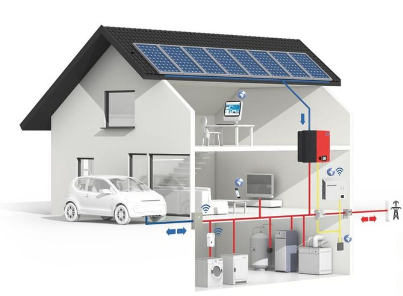
The leap in power density and the game of thermal boundaries are driving the four revolutions in solar inverter cooling technology. From the centralized H-bridge's fin air cooling to the three-level NPC topology's use of heat pipes to tame the heat source; from modular multi-levels to build a thermal redundancy defense line with phase change materials, to SiC soft switches using microchannel liquid cooling to break through the high wall of heat flux density - every topology iteration is rewriting the cooling paradigm. The essence of this evolution is the ultimate challenge of power electronics to the second law of thermodynamics under the triangular constraints of efficiency, power density, and reliability, and it will define the competitive barriers of the next generation of photovoltaic storage fusion systems.
1-Evolution of solar inverter system
The evolution of solar inverter system follows the four-step transition of heat dissipation adaptation → thermal management → thermal synergy → entropy reduction system, driving form from cabinet-type centralization to chip-level intelligent integration, power density continues to break through, efficiency and scene penetration simultaneously leap.
a. The physical form of solar inverter has undergone three-level transition:
Early centralized inverters were large in size (>1m³/MW) and weighed more than a ton; the subsequent string-type solution disassembled the power unit into 20-100kW modules, and the volume was reduced to 0.3m³/MW; the current modular design has been further advanced to 10kW sub-units, the power density has exceeded 50kW/L, and the weight has dropped to <15kg/kW.
b. Environmental adaptability shifts from passive protection to active adaptation:
· Protection level: IP54 → IP66/C5-M anti-corrosion (coastal/salt spray scenarios)
· Temperature range: -25~+60℃ → -40~+85℃ (extreme cold/desert scenarios)
· Intelligent response: Dynamic temperature control algorithm adjusts heat dissipation power in real time to match dust/high humidity environments
c. Heat dissipation demand changes qualitatively with the leap in power density:
Early forced air cooling copes with heat flux density of <100W/cm²; heat pipe technology in the three-level era solves the problem of multi-heat source temperature uniformity; SiC high frequency promotes the popularization of liquid cooling; microchannel phase change cooling is becoming a standard solution for >300W/cm², and the proportion of the heat dissipation system has been reduced from 30% to 12% of the whole machine.
2- Evolution of solar inverter system topology and thermal management
The underlying logic of the evolution of solar inverter system topology is driven by "efficiency-power density-cost":
· Changes in loss mechanism: from conduction loss dominated (H-bridge) → switching loss core (NPC) → high-frequency magnetic parts/capacitor loss (MMC) → electromagnetic compatibility loss under SiC soft switching accounts for more than 60%, pushing the heat dissipation focus from "average temperature" to "ultra-high heat flux density management";
· Power density transition: The physical limit of silicon-based IGBT (20kHz/3kW/L) was broken by SiC devices (100kHz/50kW/L), forcing the heat dissipation solution to jump from air cooling → heat pipe → liquid cooling → microchannel phase change cooling;
· Dynamic balance of cost: The proportion of heat dissipation system cost gradually decreases from H-bridge to SiC, but the unit power heat dissipation cost increases instead. It is necessary to reconstruct the thermal boundary through topology-packaging-heat dissipation collaborative design to ultimately achieve a reduction in LCOE.
 Table 1: Evolution of solar inverter topologies and thermal management
Faced with the engineering challenges of the continuous leap in power density and continuous breakthrough in heat flux density of photovoltaic inverters, the heat dissipation solution needs to be systematically upgraded:
· Evolution from air cooling to liquid cooling: to cope with the high heat flux density characteristics of new chips, significantly reduce the core temperature;
· Combination of heat pipe and phase change technology: effectively suppress the thermal shock of modular systems and extend the life of key components;
· Collaborative design and cost control: optimize the proportion of heat dissipation system through deep integration of electrical and thermal management.
As a thermal management partner, Walmate focus on direct-to-chip cooling technology and system-level thermal resistance optimization to provide feasible heat dissipation solutions for photovoltaic storage systems.
We will regularly update you on technologies and information related to thermal design and lightweighting, sharing them for your reference. Thank you for your attention to Walmate.

This article attempts to sort out the innovation path of HVDC system heat dissipation technology under the background of AI computing power explosion, focusing on two major directions: liquid cooling synergy and material upgrade. The content is compiled from industry public information. If there are any omissions, please correct them.
1- The rise of HVDC and the inevitability of upgraded cooling demand
The explosive growth of AI computing power has significantly increased the power density of data centers (single cabinet exceeds 100kW), driving the demand for high-efficiency power supply systems. Traditional UPS faces efficiency and floor space challenges, while HVDC systems are rapidly becoming the mainstream power supply solution for AI data centers with their high efficiency, low loss, small size and high reliability. This directly drives the rapid growth of the HVDC market and the surge in penetration in AI data centers. At the same time, AI demand also prompts HVDC technology to develop to higher voltage levels (such as 750V and 1000V systems) to further improve efficiency and power carrying capacity.
a. AI computing power explosion and energy efficiency requirements
In order to meet high energy efficiency standards (such as data center PUE≤1.5/≤1.3), HVDC cooling technology needs to achieve:
· Efficient cooling design, using liquid cooling technology to cope with high power density; precise control of cooling parameters.
· Optimization of heat transfer media, preferential use of deionized water, and selection of stable fluids that prevent phase separation (such as PCD) in special scenarios.
·The radiator performance is upgraded, and high thermal conductivity materials are used; the special flow channel design improves the heat exchange efficiency.
·Dynamic temperature control and monitoring, real-time monitoring of key point temperatures; equipped with diagnostic equipment to predict faults.
·Redundancy and reliability design, such as: N+1 redundant configuration of cooling system, dual-circuit chilled water pipe network to prevent single point failure.
·Emergency heat dissipation capacity, support heat dissipation under extreme working conditions.
·Environmental adaptability, ensure stable operation at an ambient temperature of 15-35℃, and take into account moisture-proof ventilation.
b. Deepening application of third-generation semiconductors (SiC/GaN)
The surge in AI computing power has promoted 800V high-voltage DC architecture to become a new trend in data centers:
·SiC/GaN gradually replaces traditional silicon-based devices with its high power density, high-frequency switching, and low loss characteristics.
·Significantly improve system efficiency.
·Reduce material costs and enhance reliability.
c. Energy efficiency advantages of HVDC vs. AC power supply and its heat dissipation impact
The requirements of HVDC architecture for heat dissipation systems are mainly reflected in high power density, efficient cooling methods, redundant design, environmental adaptability, energy efficiency optimization, and fast fault recovery. These requirements jointly determine the complexity and challenges of HVDC systems in design and operation.

Table 1: Breakdown of the root causes of differences in HVDC vs AC energy conversion losses
2- Innovation core: Liquid cooling synergy and material upgrade solutions
a. Liquid cooling system: Generational transition from edge to mainstream
Liquid cooling penetration rate has risen rapidly, AI computing power drives GPU power consumption to 1000W, forcing air cooling to transform, and edge scenarios need to adapt to the extreme temperature range of -30℃~60℃.

Table 2: Generational transition of technology paths
b. Material upgrade: a key breakthrough in coping with extreme thermal challenges
Material upgrade promotes breakthroughs in heat dissipation performance: Optimize thyristor thermal management through high thermal conductivity interface materials, combine aluminum nitride ceramic substrates (thermal conductivity ≥ 180W/mK) to enhance the heat dissipation capacity of SiC/GaN devices, and use a composite liquid cooling structure to support high power density. At the system level, N+1 redundant liquid cooling architecture, intelligent temperature control strategy and 800V withstand voltage pipeline design are used to achieve safe and efficient collaborative heat dissipation.
3-Technical Challenges and Opportunities in the Cooling Industry Chain
a. Key Challenges: Standardization and Compatibility Bottlenecks
The lack of uniformity in the interface of the chip-level cold plate and the difference in the withstand voltage of the cabinet-level pipeline (500V~800V) lead to poor compatibility and increase the cost of transformation; the cold plate and immersion technology routes are separated, and the lack of coolant insulation standards exacerbates the fragmentation of the industry; there are hidden dangers in the operation and maintenance link such as insufficient leakage detection mechanism and blank standards for coolant performance attenuation. The root cause lies in the ecological division of the three parties of chip vendors/server vendors/liquid cooling solution providers, forming an "islandization" dilemma with unclear responsibilities.
b. Collaboration Opportunities: Technical Collaboration and Industrial Collaboration
The chip layer promotes the standardization of cold plate interfaces, and the system layer links HVDC load and cooling flow rate through AI temperature control algorithms; the industrial layer relies on ODCC to establish interface and coolant standards, and shortens the deployment cycle with modular whole machines; innovates coolant regeneration technology and equipment leasing models to reduce costs, and covers leakage risks through insurance mechanisms to achieve three-dimensional collaboration of technology-industry-finance.
At present, HVDC cooling technology still faces challenges such as standardization and compatibility, but industrial collaboration has shown signs of breakthrough. This article is only a temporary observation, and we look forward to discussing optimization directions with colleagues in the industry.
We will regularly update you on technologies and information related to thermal design and lightweighting, sharing them for your reference. Thank you for your attention to Walmate.

For heat sink manufacturing, material selection and skiving fin accuracy are the key to success. Faced with the stringent requirements of ultra-thin fin and high-density fin, the core challenge is: how to balance material thermal conductivity, cost and processability? How to break through the equipment limit, achieve micron-level stable accuracy, and ensure tooth shape consistency and heat dissipation efficiency? This directly determines product performance, cost competitiveness and mass production yield.
1-Core issues and challenges of the process
a. Process essence: Layered scraping (rough → fine machining) forms high-density fin pieces
Layered scraping quickly removes excess through rough machining and ensures fin shape accuracy through fine machining, but faces three major contradictions:
· Thermal deformation control: The high cutting heat generated by rough machining causes local expansion of thin-walled fin pieces. The deformation needs to be compensated during fine machining, otherwise ellipticity errors (such as uneven spacing of heat dissipating fins) will occur.
· Stress balance: The accumulation of residual stress in layered machining causes warping of tooth pieces, especially aluminum (high thermal conductivity but low yield strength), which needs to reduce cutting force through the "small cutting depth and fast feed" strategy.
· Precision transfer: The jagged residual material left over from rough machining increases the load on the fine machining tool, which is easy to cause chatter and lead to fin thickness tolerance.
b. Two major pain points
· Heatsink material selection: Heatsink material selection needs to balance thermal conductivity, processability and cost. Through performance comparison and selection decision-making, combined with material modification and cost control, synergistic optimization can be achieved.

Table 1: Quantitative comparison of material properties and selection logic
· Equipment accuracy: Equipment accuracy optimization improves machining accuracy and tool life by suppressing cutting thermal deformation, tool wear and error, using innovative tools and thermal-mechanical coupling error compensation.

Table 2: Causal chain of precision defects
2-Material selection: the key to performance and cost
a. Thermal conductivity demand dominates
· High heat flux scenario (>100W/cm²): Copper (thermal conductivity 380W/m·K) is preferred, and its heat carrying capacity is 30% higher than that of aluminum.
Risk control: Pickling to remove the oxide layer (10% HNO₃) + benzotriazole oil film to prevent secondary oxidation, reducing tool wear by 40%.
Medium and low heat flux scenario (<80W/cm²): Pure aluminum is preferred (thermal conductivity 210W/m·K), which meets most consumer electronics needs and costs only 30% of copper.
b. Cost constraint optimization
· Cost-sensitive projects, material thinning (e.g., aluminum substrate from 4mm→2mm); waste recycling (copper chip recovery rate>95%); local composite design (copper is used only in the heat source contact area).
· Alternative solution, pure aluminum + heat pipe design, equivalent thermal conductivity 200–220W/m·K.
c. Compromise of processing difficulty
· For high fin requirements (>70mm), choose pure aluminum, the fin height limit is 120mm, and the bending resistance is stronger than copper; pretreatment, pre-annealing of aluminum (reducing residual stress) to reduce hardness fluctuations.
· For high-precision fin shape (fin thickness <0.5mm), choose 6 series aluminum, AL6063 is hardened after soft processing, and the fin thickness can be controlled to 0.25mm; Taboo, avoid direct processing of hard copper materials (easy to collapse teeth), low-temperature pretreatment is required.
3- Equipment precision optimization: the core of improving yield rate
Equipment precision is the core of the skiving process to achieve high-density fins and control deformation and wear.

Table 3: Impact mechanism of equipment error sources on yield
Ideas for optimizing the precision of skiving equipment:
· Core precision improvement: CNC substitution, replacing mechanical transmission with CNC system to eliminate indexing error; thermal deformation suppression, using cold air cutting technology and combining compensation technology to actively control thermal deformation during processing; tool strengthening, applying CBN coating and optimizing geometric structure to improve tool anti-chipping ability.
· Key achievements: Equipment processing accuracy reaches ±0.003mm (micrometer level); successfully supports the design of extreme fins with a thickness of 0.3mm and a fin height of 120mm; production yield has achieved a significant leap from 65% to 95%.
In summary, precise material matching and extreme skiving accuracy are the core barriers of radiator manufacturing. Optimized materials guarantee the foundation of performance, while micron-level precision equipment (CNC transmission, thermal deformation suppression, and durable tools) is the only way to achieve high yield and support extreme fin shape design. Only by continuously optimizing these two cores and proactively deploying advanced precision control technologies can we consolidate the market leading position of radiator processing.
We will regularly update you on technologies and information related to thermal design and lightweighting, sharing them for your reference. Thank you for your attention to Walmate.
The soaring computing power of AI servers is encountering "thermal constraints" - the power density of chips exceeds 1000W/cm² (such as NVIDIA H100), the power density of cabinets jumps from 2.4kW to 120kW, and the traditional air cooling solution reaches the physical limit of 8-10kW. The underlying logic of this "heat dissipation crisis" is the result of the quantum effect dilemma of chip architecture (the leakage rate surges below 3nm), the energy consumption imbalance of data handling (accounting for more than 90% of system power consumption), and the exponential demand for large model training (GPT-4 consumes 32.4TWh of electricity for a single training). Faced with strong policy constraints (China's PUE ≤ 1.25) and the pressure of energy efficiency, liquid cooling technology has moved from marginal experiments to mainstream and has become the key to unlocking AI computing power.
1-The underlying logic of AI server cooling requirements
a. Chip architecture and power consumption revolution
The computing power density (computing power output per unit area or per unit power consumption) and power consumption of AI chips are the core indicators for measuring their performance. The following is an analysis through three typical chip cases:

As computing power continues to upgrade, chip performance cannot be fully released due to the physical constraints of heat dissipation and energy efficiency. This "power consumption wall" phenomenon stems from:
· Heat dissipation lag, the growth rate of chip power density (>1000W/cm²) far exceeds the iteration speed of heat dissipation technology, and traditional solutions reach physical limits.
· Unbalanced energy consumption structure. At the physical level, the quantum tunneling effect below 3nm weakens energy efficiency improvement, and 3D stacking causes a sharp drop in heat dissipation efficiency by 30%-50%; at the architectural level, data handling energy consumption accounts for more than 90%, and the computing power growth rate (750 times/2 years) and memory bandwidth (1.4 times/2 years) are seriously out of balance; at the application level, large model parameter explosion (such as GPT-4 training consumes 32.4TWh) and dynamic load (instantaneous power consumption exceeds TDP by 200%) increase heat dissipation pressure.

Figure 1: The integration of storage and computing
b. Transition of cabinet power density
Cabinet power density is undergoing a revolution from general computing to AI-driven ultra-density, and the paradigm has been reconstructed from "equipment room adaptation" to "equipment definition room". AI computing power demand has forced the infrastructure to upgrade by leaps and bounds.
· Exponential transition, the global average density increased from 2.4kW/cabinet to 9.5kW/cabinet (CAGR≈12%) from 2011 to 2024, and the AI intelligent computing center has pushed the density to exceed 120kW/cabinet (such as NVIDIA GB200 NVL72), and may reach MW level in 2030.
· Core drive, the surge in AI chip power consumption (H100 single card 700W → GB200 single card 1200W) and the demand for large model training (GPT-4 single training consumes 32.4TWh of power) form a "double helix effect", forcing cabinet density to match the surge in computing power.
· Technological breakthrough, air cooling limit (8-10kW) is replaced by liquid cooling, cold plate type (20-50kW) and immersion type (50-120kW) support high density; power supply system upgraded to high voltage direct current (HVDC), efficiency> 98%; space utilization rate increased by 40% (air duct removed), liquid cooling reduces PUE to 1.08.
c. Policy and energy efficiency driven
· China's "East Data West Computing" project: mandatory requirements for eastern hub nodes PUE ≤ 1.25, western ≤ 1.2, forcing the popularization of liquid cooling technology. Taking the Inner Mongolia hub as an example, the use of immersion liquid cooling can reduce PUE to 1.08, saving more than 20 million kWh of electricity annually.
· Global carbon emission regulations: The EU CSRD directive requires data centers to disclose their full life cycle carbon footprint, and California's "Climate Enterprise Data Accountability Act" includes scope 3 emissions in mandatory disclosure. Liquid cooling technology has become the key to compliance due to the reduction of indirect emissions (such as refrigerant leakage).
· Economic benefit leverage: Liquid cooling saves 30%-50% of cooling energy compared to air cooling. Combined with the difference in peak and valley electricity prices, the investment payback period can be shortened to 3-5 years.
2- Evolution of heat dissipation technology and differentiation of technical routes
a. Liquid cooling technology: from edge to mainstream
The transition of liquid cooling from "edge experiment" to "heat dissipation base" is a rebalance between computing power density and energy efficiency, and a reconstruction of the data center value chain.
· Evolution process, marginalization stage (1960s-2010s), only used for supercomputing/military industry (such as Cray-2), limited by material corrosiveness and high cost; breakthrough period (2010s-2020s), GPU thermal density exceeded 500W/cm² (NVIDIA P100) and policy (China PUE≤1.25) drove commercial use, and the cost of cold plate transformation was reduced to 1.2 times that of air cooling; mainstream (nearly 2-3 years), AI cabinet power density exceeded 120kW (such as NVIDIA NVL72), liquid cooling TCO was 12.2% lower than air cooling, and the payback period was shortened to 3-5 years.
· Evolutionary logic, technical logic, from "air cooling to adapt to chips" to "chip-defined heat dissipation", liquid cooling becomes the core lever for releasing computing power; industrial logic, forming a positive cycle of "policy-driven standards → standards reduce costs → costs drive popularization"; ecological logic, reconstructing the data center value chain, turning the cooling system from a "cost center" to an "energy efficiency asset".
· Differentiation of technical routes, the differentiation of liquid cooling technology stems from the game between heat dissipation efficiency and transformation cost. The cold plate type prioritizes compatibility, balances costs and risks through local transformation, and adapts to medium-density scenarios; the immersion type pursues the physical heat dissipation limit, breaks through the heat density wall through system reconstruction, but faces material and operation and maintenance challenges; the spray type explores chip-level precise temperature control, paving the way for sensitive scenarios such as optical computing. The essence of liquid cooling technology differentiation is the trade-off result of the impossible triangle of "heat dissipation efficiency-transformation cost-operation and maintenance complexity". The cold plate type wins in balance, the immersion type pursues the physical limit, and the spray type aims at precise temperature control. The three together promote liquid cooling from a "technical option" to a "computing power base".
b. Chip-level cooling technology presents multi-dimensional breakthroughs
Chip-level cooling technology is undergoing a trinity of innovations in "materials-structure-control". In the short term, it is dominated by 3D microfluidics and cold plate liquid cooling (supporting kilowatt-level TDP), and in the long term, it relies on quantum cooling and photothermal synergy to break through physical limits. Its development directly determines the efficiency of AI computing power release and the evolution of data center energy efficiency.
· Materials, diamond/graphene approaches the physical thermal conductivity limit, and phase change materials solve transient thermal shock.
· Structure, microfluidics and cold plates shift from "external attachment" to "chip embedding", with shorter heat dissipation paths and higher efficiency.
· Control, solid-state active cooling chips break through volume limitations, and AI dynamic regulation realizes "heat-computing synergy".
· Core trend, the integration of the three promotes the evolution of heat dissipation from "passive heat conduction" to "chip-level active temperature control", supporting the kilowatt-level TDP requirements of single chips.
The evolution of heat dissipation technology has been upgraded from "single-point innovation" to "system reconstruction": cold plate liquid cooling leads the transformation of existing stocks with compatibility, immersion breaks through the physical heat dissipation limit, and chip-level spray technology explores precise temperature control. The three together build a layered heat dissipation system. As quantum heat dissipation and photothermal synergy technology go commercial, they will support MW-level ultra-dense computing power in a single cabinet in the future. This process is not only a revolution in the heat dissipation paradigm, but also drives data centers from "energy consumers" to "energy-efficient assets" - it is estimated that full liquid cooling can help global data centers reduce carbon emissions by 450 million tons by 2030. Heat dissipation is transforming from a cost center to the core foundation of the AI computing power economy.
We will regularly update you on technologies and information related to thermal design and lightweighting, sharing them for your reference. Thank you for your attention to Walmate.
When you see a heat sink as precise as comb teeth in an electronic device, you may not think that its peak performance was determined long before the blade touched the metal. Why are big manufacturers willing to spend a lot of money on material pretreatment? Because this step can directly upgrade the heat sink: cutting aluminum saves 20% of effort, copper heat sinks can be used for 3 more years, and even 12 cm high heat sinks can be cut in one go. This article introduces how to "massage and loosen bones" of metal through scientific means, so that hard metal can be obediently transformed into a perfect heat sink.
1-Why is pretreatment the "invisible engine" of the skived heatsink?
a. Manufacturing challenges of high-precision heat sinks
· Residual stress concentration: The residual stress from the rolling or casting process of the raw materials is released during skiving, causing the substrate to warp.
· Material softening: Aluminum, copper and other materials soften locally due to temperature rise (aluminum 40-60℃, copper 80-120℃) during the cutting process, causing the tooth to collapse or increase burrs.
· Surface oxidation: Copper is easily oxidized in the air to form a CuO layer (high hardness and high brittleness), which aggravates tool wear and shortens tool life.
b. Pretreatment - the key bridge from "metal raw materials" to "precision tooth slices"
· Material performance optimization, recrystallization annealing of aluminum and copper materials respectively, eliminates the residual stress generated during the rolling process, and the uniformity of material hardness can be significantly improved.
·Surface state control, using chemical cleaning to remove the oxide layer on the surface of the material, such as copper can be pickled with 10% HNO₃, and the surface roughness can be reduced to 0.4μm after treatment, effectively reducing tool adhesion; or passivation treatment of aluminum, such as anodizing aluminum to form a 5-10μm thick Al2O3 film to prevent secondary oxidation during processing.
c. How does pretreatment technology improve processing efficiency?
·Shorten the processing cycle, the cutting resistance of the material is reduced after pretreatment, allowing for increased feed speed.
·Reduce rework rate: Stress pre-release greatly improves the flatness pass rate of the substrate, eliminating the secondary correction process.
2-The foundation of pretreatment technology: the integration of material science and technology
The core of pretreatment technology is to customize the process logic based on material properties to solve the inherent contradictions of high thermal conductivity materials such as aluminum and copper in gear skiving.
a.Material properties determine pretreatment logic

·Pretreatment of aluminum materials: annealing at 300–350℃×2h can eliminate rolling stress and improve hardness uniformity by 40%; surface treatment can be selected by anodizing to generate 5–10μm Al₂O₃ film or chemical passivation (chromate treatment) to inhibit oxidation during processing.
·Pretreatment of copper materials: annealing at 500–600℃×1h can soften the material, reduce hardness from 80HB to 45HB, and reduce cutting force by 30%; pickling uses 10% HNO₃ solution to remove the oxide layer. When the CuO thickness exceeds 1μm, the tool wear rate will increase by 50%.
b. Core contradiction: Processing paradox of high thermal conductivity materials
·Contradiction point: high thermal conductivity (such as 380 W/m·K for copper) is the core advantage of the heat sink. High thermal conductivity causes cutting heat to be quickly transferred to the tool, accelerating wear (the tool life of copper processing is only 1/3 of that of aluminum).
Pretreatment scheme, balance between thermal conductivity and machinability, such as low-temperature pretreatment of copper materials to reduce cutting temperature rise or gradient material design; oxide layer management, such as retaining the dense Al2O3 film of aluminum materials to reduce friction; coating the copper materials with benzotriazole oil film after pickling to block secondary oxidation.
3-Core pretreatment methods
a. Mechanical pretreatment: "paving the way" for processing
Surface cleaning (sandblasting/polishing), removing oxide layers, oil stains and burrs, improving surface roughness (Ra value), enhancing coating adhesion or subsequent pickling effect.
b. Chemical pretreatment: activating material surface activity
Through physical cleaning (decontamination), chemical modification (conversion film formation) and surface performance improvement, the material surface is transformed from an inert state to a highly active state. The core lies in balancing surface roughness, chemical functional group density and corrosion resistance, thereby providing an ideal substrate for subsequent processes.
c. Heat treatment: reshaping the material microstructure
By precisely controlling the heating, insulation and cooling processes of the material, the microstructure is reorganized and optimized. The core lies in using thermal activation mechanisms to drive atomic diffusion, phase change and defect reorganization, thereby giving the material new performance characteristics.
d. Composition control: full process management from smelting to molding
Composition control is the core technology of material manufacturing. Through the selection of raw materials, precise smelting control and molding parameter optimization, combined with digital detection, fine control of fluctuations, and improved performance.
4-Aluminum vs. Copper: Differentiated Pretreatment Strategies
Due to the significant differences in the physical and chemical properties of aluminum and copper, pretreatment strategies need to be designed specifically to solve their respective processing pain points.

5-How does pretreatment become an efficiency "amplifier"?
a. Collaboration with skiving processing
· Reduce tool wear: After pretreatment, the residual hard oxide on the surface is reduced, the tool life of the skiving tool is extended, and the chipping rate of high-density fins pieces is reduced.
· Improve processing accuracy: Sandblasting pretreatment eliminates material internal stress, reduces the tooth height error from ±0.5mm to ±0.1mm, and meets the requirements of high-multiple teeth (tooth height/substrate thickness ≥10).
b. Collaboration with surface treatment
· Enhance coating adhesion: After passivation pretreatment, the coating adhesion test pass rate can be significantly improved.
· Reduce contact thermal resistance: Pretreatment forms a uniform microporous structure, which reduces the thermal resistance of the radiator and heat pipe welding interface by 15%-20%.
c. Collaboration with surface CNC processing
· Reduce secondary processing defects: After chemical cleaning to remove oil stains, the burr rate of CNC milling aluminum is reduced by 60%, and the tapping and sliding defects are reduced by 50%.
d. Effect of pretreatment on production efficiency
· Improved yield rate: By optimizing the chemical and mechanical pretreatment processes, the yield rate of skived heatsink and CNC processing has been significantly improved, and product quality has been guaranteed.
· Shortened processing cycle: After pretreatment, aluminum processing does not require separate deburring, and the processing time of a single piece is greatly shortened. The processing speed of the automated sandblasting line is increased, and production efficiency is significantly improved.
· Reduced energy consumption and costs: Mechanical pretreatment is used instead of chemical pickling, and processing energy consumption is reduced. After pretreatment, the hardness of the material is reduced, the mold loss is reduced, and the production cost is effectively reduced.
We will regularly update you on technologies and information related to thermal design and lightweighting, sharing them for your reference. Thank you for your attention to Walmate.
As the global energy structure transformation accelerates, the role of energy storage systems in power frequency regulation, new energy consumption and other scenarios is becoming increasingly prominent. As the core carrier, the environmental adaptability design of the ess battery enclosure must take into account extreme climate tolerance, structural strength and long-term reliability. Starting from the scenario requirements, this article sorts out the key technical paths of climate adaptability, analyzes the design challenges and innovation directions, and provides a reference for the development of high environmental adaptability ess battery enclosure.
1-Differentiation of energy storage market scenarios and refined management trends
a. Scenario differentiation map: coupling of regional characteristics and technical requirements
The energy storage market shows significant regional differentiation, and technical solutions need to adapt to climate conditions, grid characteristics and application scenarios:
· Extreme climate scenarios:
High temperature desert environment: The enclosure needs to withstand high temperatures above 50°C (the heat island effect inside the container can reach 53.3°C), pass IP55/IP67 protection level certification, and use multiple measures such as sand-proof cotton and sealant to resist wind and sand erosion.
High altitude/low temperature environment: At low temperatures of -40°C, it is necessary to integrate battery cell preheating technology, optimize the cooling capacity attenuation of the liquid cooling system (the operating lower limit is extended to -30°C), and strengthen electrical insulation to cope with the arc risk caused by thin air.
· Power system adaptation scenarios:
European power grid frequency regulation needs to meet dynamic power regulation (47.5-51.5Hz range) and be compatible with the requirements of the auxiliary service market; North American photovoltaic storage integration projects need to support 1500V DC architecture and fast charging and discharging switching (≤100ms), and pass thermal runaway propagation tests to ensure safety.
·Industrial and commercial energy storage scenarios:
Compact design uses direct cell integration technology (space utilization increased to 33%), modular solutions support flexible expansion (15-921kWh), and integrates intelligent operation and maintenance functions to reduce the cost of the entire life cycle.
b. Refined business strategy, transformation from product delivery to value service
·Customized technical solutions: In view of the high transmission cost in isolated areas, the configuration of a long-term energy storage system of more than 4 hours can reduce the investment in grid upgrades by 30%; the grid-type energy storage system supports multi-scenario compatibility and improves grid stability.
·Full life cycle service: Optimize initial investment and operation and maintenance costs through the LCoS (levelized cost of storage) model, the intelligent operation and maintenance platform integrates electricity price data and load forecasts, dynamically optimizes charging and discharging strategies, and increases revenue by more than 15%.
2-Key technical paths for climate tolerance
a. Thermal management-structure collaborative design
·Liquid cooling technology-led:
Cold plate liquid cooling: using serpentine microchannel cold plate (channel width ≤ 2mm), temperature difference control ≤ 3℃, the transformation cost is 15%-20% higher than the air cooling system, and the battery life is increased by 30%.
Immersion liquid cooling: direct heat dissipation through dielectric coolant, heat conduction efficiency is increased by more than 50%, but the cost of coolant and maintenance complexity need to be balanced, and it is mostly used in high-end scenarios.
·Structural integration optimization:
The integrated design of flow channel-bottom plate is combined with stir friction welding process, the weld strength reaches 95% of the parent material, the seismic performance meets IEC standards, and the weight of the enclosure is reduced by 18%.
b. Climate erosion protection system: material revolution and sealing technology innovation
·Material selection:
The aluminum alloy box achieves C5 level corrosion protection through anodizing, and the salt spray test reaches 3000h without corrosion; the carbon fiber composite material reduces weight by 35%, and the wind pressure resistance reaches 2.5kPa.
·Sealing technology:
The dynamic sealing structure adopts EPDM rubber, polyurethane foam layer and silicone sealant for triple protection, and the laser welding process makes the air tightness reach 10⁻⁷ Pa·m³/s.
c. Extreme climate response strategy: active defense and intelligent regulation
·High and low temperature adaptability:
The composite insulation layer (thermal conductivity ≤0.018W/m·K) is combined with the electric heating film to maintain the temperature difference between the inside and outside of the box above 50℃; the pulse self-heating technology reduces energy consumption by 70%.
·Anti-wind and sand design:
Positive pressure ventilation system (dust removal efficiency ≥95%) and bionic micro-groove surface design, the dust concentration is controlled to ≤0.1mg/m³, and the surface dust is reduced by 60%.
3-Core challenges and requirements of ESS battery enclosures design
a. Definition of environmental adaptability
It needs to meet multi-dimensional indicators such as mechanical strength (impact resistance, earthquake resistance), chemical stability (salt spray resistance, UV resistance) and thermal management performance.
b. Structural strength requirements
Internal partitions and reinforcement ribs optimize stress distribution, and the load-bearing structure balances pressure; aluminum alloy frames combined with composite panels achieve lightweight (31% weight reduction) and high rigidity.
c. Market driving factors
Policy orientation: The construction of large domestic wind and solar bases promotes high environmental standards; compulsory certification in overseas markets (such as Australia's AS/NZS 4777.2) accelerates technology upgrades.
Economic requirements: Liquid cooling systems reduce LCoS, and have significant advantages in high charge and discharge rate (1C) scenarios.
4-Multi-dimensional structural strength design system
a. Material innovation and composite structure
High-performance aluminum alloy (tensile strength ≥ 270MPa) and magnesium alloy bracket work together to reduce weight; composite sandwich structure (aluminum panel + foam aluminum core layer) takes into account both lightweight and impact resistance.
b. Modular and scalable architecture
Standardized interfaces support rapid expansion of battery clusters, and flexible manufacturing processes (friction stir welding/laser welding) improve production line compatibility and adapt to the needs of mixed installation of multi-size battery cells.
The environmental adaptability design of the ESS battery enclosure is the product of deep coupling of technology iteration and scenario requirements. It is necessary to achieve a leap in reliability through multi-dimensional structural optimization and climate protection technology innovation. Future technological development will focus on intelligent dynamic temperature control (such as AI-driven thermal management strategies), low-carbon material processes (application of bio-based composite materials) and global standardization certification (covering multi-regional climate conditions) to cope with extreme environments and diversified market challenges. By strengthening structural strength, lightweight design and full life cycle cost optimization, energy storage systems can effectively support the large-scale application of new energy and provide highly adaptable infrastructure guarantees for the low-carbon transformation of the global energy system.
We will regularly update you on technologies and information related to thermal design and lightweighting, sharing them for your reference. Thank you for your attention to Walmate.
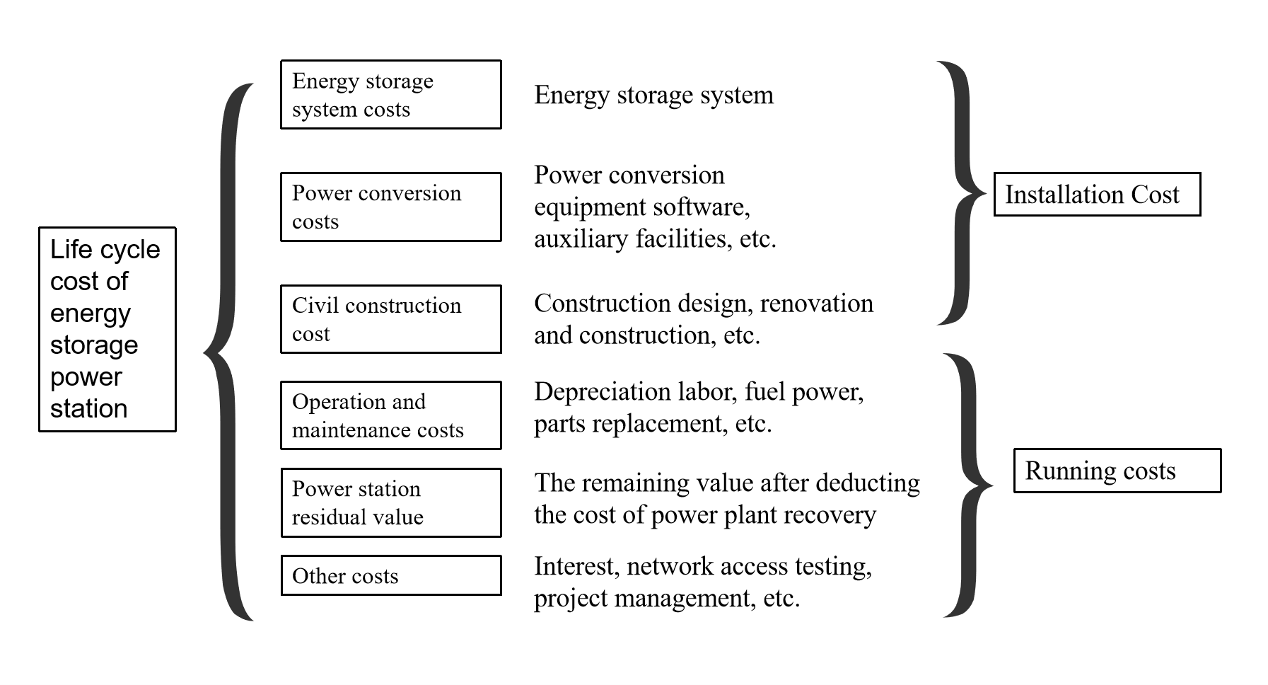
The application process of the main materials of the ESS Battery Enclosure is essentially a balancing process between lightweight requirements, thermal management efficiency and full-cycle costs. From steel to aluminum alloy to composite materials, each iteration is accompanied by process innovation (such as welding technology, modular design) and functional integration (liquid cooling + fire protection + sealing).
1-Lightweight logic
a. Material selection and substitution logic
· Initial stage (before 2020): steel and galvanized steel plates dominate
Material characteristics: Steel (density 7.8g/cm³) has become the mainstream due to its low cost and mature technology, but it is heavy and easy to corrode. Galvanized steel plates (anti-sand and wear Class 4) still face the risk of rust after long-term use and have high maintenance costs.
Application limitations: The weight of the enclosure accounts for more than 40%, the system energy density is low, and customized welding leads to a long installation cycle, which is difficult to match the demand for distributed energy storage.
· Breakthrough period (2020-2024): Diversified application of aluminum alloy and stainless steel
Popularization of aluminum alloy: The density (2.7g/cm³) is 65% lower than that of steel, and the thermal conductivity coefficient of 237W/mK is suitable for liquid cooling technology. The integrated design integrates the liquid cooling channel and the bottom plate through stir friction welding, reducing connectors and improving sealing; the typical double-layer structure solution (outer galvanized steel plate anti-wind and sand + inner aluminum-magnesium alloy temperature control) achieves a 12% increase in system efficiency.
Stainless steel optimization: 316L stainless steel is resistant to chloride ion corrosion for more than 2000 hours, and combined with silicone seals to form a high humidity scenario solution.
· Mature stage (2024 to present): Composite materials and functional integration
SMC composite materials: Glass fiber reinforcement (density 1.67g/cm³) weighs only 21% of steel, and compression molding realizes special-shaped structure design; "sandwich" composite structure (SMC+aerogel) has a fire resistance limit of 2 hours and a simultaneous weight reduction of 30%.
Carbon fiber exploration: Tensile strength 300-1200MPa, density 1.5-2.0g/cm³, limited by cost (5-8 times that of steel), it is mostly used for local reinforcement in high-end scenarios.
The core of material lightweighting lies in the optimization of density-strength ratio. See the material performance comparison in the table below. By replacing high-density materials (such as steel) with aluminum alloys or composite materials, the weight can be significantly reduced while ensuring strength (such as compensating for strength loss through topological optimization), thereby improving energy density and transportation efficiency.

b. Structural optimization technology
Structural optimization reconstructs the mechanical structure of the box through innovative design methods, streamlining materials and processes while maintaining load-bearing performance. Aluminum alloy tailored welding technology uses advanced welding technology to achieve significant thinning of wall thickness, combined with the integrated design of flow channel and frame to reduce redundant connection nodes and reduce the risk of sealing failure. Stamping brazing technology uses mold forming technology to create an integrated curved thin-wall structure, greatly reducing the use of traditional fasteners, and integrating surface treatment technology to enhance corrosion resistance, effectively reducing the operation and maintenance costs of the entire life cycle. The two technologies synergistically improve production efficiency and structural reliability by reducing processing links and material redundancy, significantly reducing the unit energy storage cost, while ensuring the long-term operation stability of the equipment under complex working conditions.

c. Manufacturing process innovation
Structural design optimization and efficiency improvement:
Integrated integration: The liquid cooling channel is integrated with the bottom plate of the enclosure, reducing 30% of the connectors, and improving both sealing and heat dissipation efficiency.
Modular design: The standardized interface is compatible with multiple materials, the installation efficiency is increased by 50%, and it is suitable for rapid deployment in multiple scenarios.
Advanced technology reduces costs and improves efficiency:
High-precision automation: Laser cutting + robot welding, material utilization rate increased by 15%, and production cycle shortened by 40%.
Digital simulation: CAE optimizes process parameters, the number of mold trials is reduced by 50%, and the yield rate exceeds 98%.
2-Core elements of full-cycle cost control
a. Cost composition model
The full-cycle cost (LCOS) includes:
· Initial investment cost (C_mv): equipment procurement (accounting for more than 50%) and construction.
· Operating cost (C_ps): charging electricity, labor management, energy loss (such as charging cost increases by 33% when conversion efficiency is 75%).
· Operation and maintenance cost (C_om): equipment maintenance, fault repair, spare parts replacement (accounting for 20-30% of life cycle cost)
Formula expression: CEss=α⋅EBESS+β⋅PBESS+Cps+ComCEss=α⋅EBESS+β⋅PBESS+Cps+Com
Among them, lightweighting directly affects the initial investment by reducing E (energy demand) and P (power demand)

Figure 1. Life cycle cost of energy storage power station
b. The impact of lightweight on cost

3-Key strategies for balancing lightweight and performance
a. Balance between strength and weight
Local reinforcement: Use steel to reinforce stress concentration areas (such as bolted joints), and use lightweight materials in other areas.
Bionic structure design: For example, leaf vein-shaped liquid cooling pipes, which can reduce weight and improve heat dissipation efficiency.
b. Optimization of heat dissipation performance
Material thermal conductivity matching: Aluminum alloy (237 W/mK) is better than steel (50 W/mK), which is suitable for liquid cooling systems.
Thermal management integration: Integrate the cooling plate and the box to reduce the weight of additional heat dissipation components.
c. Protection performance guarantee
Multi-layer sealing: Double protection of colloid sealing + mechanical compression is adopted to meet IP67 standards.
Fireproof design: The "sandwich" cabin structure (high temperature resistant layer + fireproof layer) achieves a 2-hour fire resistance limit.
The underlying logic of lightweight and cost control of ESS Battery Enclosure is to reduce the full-cycle resource consumption while ensuring performance through the three-dimensional synergy of material substitution-structure optimization-process innovation. Its essence is a comprehensive game of improving energy density, optimizing operation and maintenance efficiency, and recycling materials, and it is necessary to find the best balance between technical feasibility and economic efficiency.
We will regularly update you on technologies and information related to thermal design and lightweighting, sharing them for your reference. Thank you for your attention to Walmate.
The safety evolution of the energy storage industry is a systematic change driven by the synergy of technology iteration and safety standards. From the reconstruction of heat dissipation paths, coordinated protection of materials and structures to integrated thermal management, this process reflects the industry's underlying logic for thermal runaway protection - from passive defense to active suppression, and from a single dimension to a multi-level coupling upgrade.
1- The "impossible triangle" of energy storage technology and strategies to resolve core contradictions
a. The contradictions of the "impossible triangle" of energy storage technology are mainly manifested in the mutual checks and balances of multiple dimensions:
The development of energy storage technology faces a complex balance between energy density, safety and cost. Although high-activity materials can improve energy density, they also significantly increase the risk of thermal runaway; while system-level safety design (such as liquid cooling temperature control technology) can reduce risks, it is often accompanied by a loss of energy density. In addition, the introduction of active protection systems and intrinsic safety technologies can improve safety, but significantly increase the cost of non-battery parts. These contradictions reveal the multiple constraints that need to be solved in the evolution of energy storage technology.
b. Strategies to resolve core contradictions:
Material innovation: The application of new electrolyte materials significantly delays the propagation time of thermal runaway while taking into account high energy density; sodium-ion batteries maintain reasonable energy density while reducing costs through the optimization of negative electrode materials; the introduction of nano-composite materials greatly increases the theoretical capacity.
System optimization: Advanced liquid cooling technology significantly improves heat dissipation efficiency through precise temperature control, while reducing operation and maintenance costs; dynamic reconfigurable battery networks enhance system availability through rapid topology adjustment.
Intelligent control: The artificial intelligence early warning system has greatly improved the accuracy of risk prediction through multi-dimensional data fusion; the progress of energy conversion technology has significantly improved system efficiency. Policy and business model innovation has accelerated the implementation of technology. For example, the shared energy storage model has reduced the pressure of single-point investment, and the cascade utilization has further optimized the cost of the entire life cycle.
2-Evolution rules
a. Fusion innovation of technical paths
Intelligent early warning driven by multi-source data: The new generation of monitoring systems integrates multi-dimensional sensor data such as gas, pressure, and acoustic signals, and combines dynamic failure models with historical data analysis to significantly reduce the false alarm rate and advance the warning time.
Thermal management and fire linkage design: Liquid cooling technology combined with dynamic temperature adjustment algorithm to achieve precise temperature control, fire protection system and battery management are deeply integrated to form a multi-level linkage strategy, which effectively suppresses the spread of thermal runaway.
Coordinated optimization of materials and structures: High-temperature resistant insulation coating replaces traditional fireproof materials, significantly prolonging the heat spread blocking time; anti-collision reinforcement and directional pressure relief channels are introduced in the structural design to improve the ability to resist mechanical impact.
b. Gradual deepening of protection levels
Progressive protection from battery cells to systems: Early risk monitoring is achieved through embedded sensors at the battery cell level; composite detectors and phase change materials are used at the module level to suppress local heat accumulation; a collaborative monitoring platform is built at the system level to achieve full life cycle protection.
From passive response to active defense: The new standard promotes the development of active defense technology. For example, the intelligent battery management system cuts off the risk path at the beginning of charging through dynamic impedance analysis, and the active anti-condensation technology eliminates environmental hazards.
Multi-dimensional collaborative protection: Thermal-electrical-mechanical collaborative design strengthens the overall safety of the system; fire protection and operation and maintenance collaborative monitoring covers the entire manufacturing and transportation links to reduce the risk of false alarms.
3-Evolution process
a. Iteration of heat dissipation technology
Liquid cooling technology has become mainstream: liquid cooling systems significantly reduce the temperature difference of battery clusters through efficient temperature uniformity, extend life and improve safety; immersion liquid cooling technology further breaks through the heat dissipation limit and supports high-rate charging and discharging scenarios.
Structural optimization improves heat dissipation efficiency: multi-channel parallel design realizes uniform flow of coolant, and the integration of heat insulation and cooling functions blocks the heat spread path.
b. Material and structural innovation
High-safety material system: high-temperature resistant diaphragms and ceramic coatings significantly delay the chain reaction of thermal runaway; lightweight composite materials improve structural strength and protection performance while reducing weight.
Battery cell and module innovation: new battery cell design reduces circulation and extends life by optimizing internal structure, and module integration technology improves space utilization and heat dissipation efficiency.
c. Thermal management integration
System-level integrated design: the integrated solution deeply integrates battery management, fire protection and thermal management, supports flexible deployment and adapts to extreme environments.
Intelligence and collaborative control: artificial intelligence models predict battery status in real time and optimize energy distribution, and fire protection systems and thermal management are linked to achieve rapid response.
Full life cycle management: Closed-loop management from design to retirement combined with digital monitoring and cloud-based health assessment significantly improves system reliability.
Conclusion
The safety innovation of energy storage technology is not only the result of technological iteration, but also the reconstruction of the underlying logic of the energy system. Through the deep integration of materials, structures and intelligence, the industry is breaking through the multiple shackles of energy density, safety and cost, and building a three-dimensional protection network from micro-cells to macro systems. The synergy of liquid cooling technology and dynamic early warning, the complementarity of high-temperature resistant materials and lightweight design, and the closed-loop logic of full life cycle management jointly outline the future vision of high-safety and high-efficiency energy storage systems. With the breakthroughs in cutting-edge technologies such as quantum materials and solid-state batteries, the energy storage industry will accelerate towards a new era of intrinsic safety and large-scale application, injecting lasting power into the low-carbon and intelligent transformation of the global energy system.
We will regularly update you on technologies and information related to thermal design and lightweighting, sharing them for your reference. Thank you for your attention to Walmate.

As energy storage systems evolve towards large capacity and high energy density, the size matching and compatibility design of ESS Battery Enclosures have become the core issues for improving system efficiency and reliability. This article combines the latest engineering design cases, patented technologies and industry trends to analyze from three dimensions: space utilization, modular compatibility, and cell arrangement and support design.
1- ESS Battery Pack Enclosure Space Utilization Optimization
The improvement of space utilization of energy storage system integration is essentially a two-way drive of technology iteration and scenario requirements. Through the collaborative innovation of technologies such as large-capacity battery cells, modular architecture, and liquid cooling integration, the industry is moving from "extensive stacking" to "extreme space reuse".
a. Application of large-capacity battery cells: energy density and efficiency leap
Summary of ideas: The application of large-capacity battery cells is essentially to reduce the internal structural level of the battery pack and directly improve the space utilization of the battery cell to the battery pack. Traditional battery packs adopt a three-level integration mode of "battery cell → module → battery pack", and the module structure (crossbeam, longitudinal beam, bolts, etc.) leads to low space utilization. Large-capacity battery cells can directly skip the module level by lengthening or increasing the volume of the single cell, and use CTP (Cell to Pack) technology to directly integrate the battery cell into the battery pack.
Technical core: Use 600Ah+ ultra-large battery cells to reduce the number of battery cells and connection points, and increase the single cell capacity.

b. Spatial reuse and cost optimization: from "component stacking" to "multi-dimensional reuse"
Summary of ideas: Spatial reuse and cost optimization are two sides of the same coin, and their underlying logic is to break the physical and cost boundaries of traditional energy storage systems through structural simplification, functional integration, material iteration and standardized design.
The core of spatial reuse is to reduce the intermediate links through the extreme simplification of the structural level. For example: the two-in-one design of the high-voltage box: Jiangsu Trina Energy Storage's patented technology combines two high-voltage boxes into one, sharing the total positive/negative relay and electrical connection, reducing the horizontal space occupancy by 30%, and reducing the cost of electrical components by 15%.
Cross-domain reuse of functional modules, integration of structural parts and heat dissipation channels, such as integrating the liquid cooling plate with the bottom plate of the box, and sharing the space between the liquid cooling pipe and the structural support, reducing 15% of independent heat dissipation components; the battery body as a structural part: BYD's blade battery provides support strength through the long and thin side walls of the battery cell, eliminating the module frame, and increasing the space utilization rate to 60%-80%.
Deep optimization of electrical topology, for example, high-voltage cascade topology reduces the number of parallel circuits by increasing the capacity and voltage level of single cells (such as Huawei's smart string energy storage), reducing the physical space of the battery stack by 20%, and shortening the system response time by 50%. Shared relay design, Jiangsu Trina Energy Storage's two-in-one high-voltage box allows two lines to share the same relay, reducing the number of relays and cable length by 50%, and improving installation efficiency by 30%.
2- Cell arrangement and support design: load-bearing, heat dissipation and vibration resistance balance
The essence of cell arrangement is the game between space utilization, heat distribution and mechanical stability. The physical form and arrangement direction of the cell directly affect the space filling efficiency:
a. Optimize the arrangement of cells
Inverted cell design: turn the cell explosion-proof valve downward, so that the thermal runaway exhaust and the bottom ball-proof space are shared, releasing the cell height space and achieving volume utilization.
Lying cell layout: optimize the space utilization in the height direction of the battery pack, increase the proportion of active materials, and significantly increase the volume utilization rate than the vertical cell.
Ultra-long and thin cells: reduce the number of cells per unit volume through the cell length and thinness design, and improve the grouping efficiency.
b. Coupling design of heat dissipation and load-bearing: aims to achieve dual optimization of efficient heat dissipation and structural strength through collaborative innovation of structure, materials and processes.
Structural design path:
Integrated structure, such as conformal design of liquid cooling plate and support beam: embed the liquid cooling channel into the aluminum alloy support beam to reduce independent components and improve space utilization;

Layered and compartmented layout, stacking the battery pack, liquid cooling system, and BMS in layers to reduce the mutual interference between heat flow and mechanical stress;
Bionic mechanics optimization, such as honeycomb/corrugated structure, designing honeycomb or corrugated core layer in the aluminum alloy support frame (such as Mufeng.com patent solution), absorbing vibration energy through deformation, and optimizing the heat dissipation path.
Material innovation path:
Integrated heat conduction and load bearing, such as aluminum alloy composite fiber material (thermal conductivity ≥ 200 W/m·K, strength +30%); intelligent material, phase change filling layer (PCM) absorbs heat and releases slowly, temperature difference ±1.5℃; lightweight damping: elastic silicone cushion absorbs vibration (damping +40%).
Process implementation path:
Precision molding process, such as extrusion molding: used to manufacture aluminum alloy liquid-cooled beams with complex flow channels;
Surface treatment technology, such as generating a ceramic oxide layer on the surface of aluminum alloy to improve corrosion resistance (salt spray test ≥1000h), while enhancing heat dissipation efficiency (surface emissivity increased by 20%);
Intelligent assembly process, dynamic preload adjustment, such as integrating pressure sensors and electric actuators to adjust bolt preload (5-20kN) in real time to avoid overpressure damage to the battery cell.
c. Coordinated design of load-bearing and vibration resistance of the support structure: The support system needs to meet the dual requirements of static load-bearing (battery cell weight + stacking pressure) and dynamic vibration resistance (transportation/earthquake shock).
3- Modularity and compatibility: standardized interface and scalable architecture
The essence of standardized interface adapting to multi-size batteries is to achieve flexible expansion of battery specifications on a unified platform through collaborative innovation in mechanical, electrical and thermal management. The current technology has shifted from static compatibility to dynamic adjustment, and will evolve towards intelligence, lightweight and cross-scenario integration in the future.
a. Collaborative innovation of mechanical structure:
Standardization of mechanical interface: define unified connection device size.
Modular battery pack/cabinet design: build scalable modules and battery cabinets through standardized size battery cells (such as 280Ah, 314Ah batteries), supporting flexible combinations of different capacity requirements.

Figure 1-280Ah ESS Battery Pack Enclosure
b. Dynamic adjustment of electrical system
Standardized communication protocols and interfaces, such as BMS compatibility: formulate a unified BMS (battery management system) communication protocol to support seamless connection with PCS and battery cells of different manufacturers; dynamic power adjustment, through virtual inertia control and multi-time scale optimization algorithm, to achieve real-time adjustment of active/reactive power; and adaptive electrical parameter matching design.
c. Intelligent adaptation of thermal management system
Graded thermal management solutions, such as the use of flame-retardant high-rebound foam, thermal conductive glue and other materials at the battery level to balance the insulation and heat dissipation requirements and inhibit heat diffusion; the integrated design of the module-level integrated liquid cooling plate and the insulation layer to improve the cycle life; the system level dynamically adjusts the cooling capacity through variable frequency compressors and multiple cooling branches.
Intelligent monitoring and prediction, multi-sensor fusion. Arrange temperature sensors at key locations such as battery poles and large surfaces to achieve high-precision temperature acquisition; digital twin technology optimizes the heat dissipation strategy in real time through cloud monitoring and predictive maintenance.
4-Summary
The optimization of ESS Battery Enclosure space has shifted from single structural improvement to multi-dimensional collaborative innovation:
The fusion of materials, structure and algorithm, such as the combination of carbon fiber enclosure + CTP technology + AI layout algorithm, will become the mainstream.
Modularization and standardization are accelerating, and the standardized design with Pack as the smallest functional unit will promote the industry to reduce costs and increase efficiency.
The deep binding of thermal management and space utilization, immersion liquid cooling and dynamic temperature control technology further release the potential of space.
For more information on cost control of ESS battery pack enclosures, please read the following article:Lightweight design of ESS Battery Enclosure: analysis of material selection and full-cycle cost control
We will regularly update you on technologies and information related to thermal design and lightweighting, sharing them for your reference. Thank you for your attention to Walmate.

With the explosive growth of AI computing power and the continuous increase in power density of data centers, traditional air cooling technology can no longer meet the heat dissipation needs. Liquid cooling technology has become a must with its advantages of efficient heat dissipation, energy saving and consumption reduction. In liquid cooling technology, the competition between cold plate and immersion cooling is particularly fierce. This article will analyze the advantages and disadvantages of the two from the perspectives of technical characteristics, application scenarios, cost-effectiveness and future trends, and explore their future dominant directions.
1- Cold plate vs Immersion cooling: cold plate type has strong compatibility, and immersion type has higher heat dissipation efficiency
a. Cold plate liquid cooling: a "reformist" with smooth transition
Strong compatibility: No need to significantly modify the server structure, it is compatible with the infrastructure of the existing air-cooled data center, with low modification cost and short cycle.
High safety: The coolant does not come into direct contact with electronic components, the risk of leakage is low, and the risk can be further reduced through modular design (such as quick-change joints and redundant pipes).
High maturity: Cold plate liquid cooling has been widely used in scenarios such as Alibaba Cloud Qiandao Lake Data Center and Intel cooperation projects, accounting for 90% of the current liquid cooling market.
Limitations: The cold plate liquid cooling can only cover some high-power components (such as CPU and GPU), and the rest of the heat still needs to rely on air cooling to assist heat dissipation. The PUE value is usually 1.1-1.2, slightly higher than the immersion type.
b. Immersion cooling: an "innovator" with efficient heat dissipation
Immersion cooling completely immerses the server in insulating coolant, and achieves full device heat dissipation through direct contact. Its core advantages include:
Extreme energy efficiency: The thermal conductivity of liquid is 20-30 times that of air, PUE can be as low as 1.05, and the heat dissipation efficiency is increased by more than 3 times.
Space saving: The volume of the cooling system is only 1/3 of that of air cooling, and the power density of a single cabinet can reach more than 50kW, which is suitable for high-density scenarios such as AI supercomputing.
Silent and environmentally friendly: No fans are required, noise is reduced by more than 90%, and there is no dust pollution, which extends the life of the equipment.
Challenges: Immersion requires customized servers, the cost of coolant accounts for up to 60% (such as fluorinated liquid), and the initial investment is high, and the ecological compatibility needs to be improved.

2-Differentiation of application scenarios: medium- and short-term cold plate dominates, long-term immersion cooling potential is released
a. Cold plate cooling: "cost-effective choice" for stock transformation and new IDC construction
Renovation of old data centers: Cold plate cooling can quickly adapt to the existing air-cooled architecture, with a short transformation cycle and controllable costs. For example, the modular solution cooperated by Intel and Bih reduces the difficulty of deployment through standardized cold plate design.
Medium and high density computing power scenarios: Cold plate cooling already supports 130-250kW power per cabinet (such as NVIDIA B series GPU), meeting most AI training needs.

Data center liquid cold plate-micro channel high-efficiency heat dissipation
b. Immersion cooling: "ultimate solution" for supercomputing and green data centers
Ultra-high density computing power: The cabinet power of the next generation of chips (such as NVIDIA Rubin series) will exceed 1000kW, and immersion cooling will become the only feasible solution.
Green energy-saving needs: The PUE of immersion cooling is close to 1.05, and the waste heat recovery efficiency reaches 90% (such as Lenovo's solution), which is in line with the "dual carbon" target policy.

Immersion cooling of server
c. Current liquid cooling market situation
Cold plate cooling dominates the current market: In 2025, cold plate accounts for 80%-90% of the liquid cooling market, and immersion cooling accounts for less than 10%. In addition, standardized interfaces have been formed (such as Intel's OCP cold plate design), and solutions from manufacturers such as Inspur and Sugon have strong compatibility. The domestic "East Data West Computing" project requires that the PUE of new data centers be ≤1.25, and cold plate cooling has become the first choice for transition.
Immersion cooling is ready to go: Sugon Digital C8000 phase change immersion solution achieves PUE 1.04, and Alibaba Cloud's "Kirin" data center verifies the feasibility of single-phase immersion.High-power chips such as NVIDIA B200 GPU (1000W+) force immersion cooling applications, and liquid cooling computing power density increases by 30%-50%.The EU plans to ban fluorinated liquids in 2028, and domestic hydrocarbon/silicone oil coolant research and development is accelerating (such as Sinopec's "Kunlun" series).
3-Authoritative opinion PK
Cold plate faction: Cold plate is the "icebreaker" of liquid cooling popularization, and will still bear 80% of the incremental liquid cooling market in the next five years. Immersion cooling needs to wait for the chip power consumption to break through the critical point.
Immersion faction: Phase change immersion is the ultimate form of liquid cooling, and cold plate is only a transitional solution. When the power consumption of a single chip exceeds 800W, immersion will become the only choice.
Neutral faction: The differentiation of technical routes reflects the stratification of computing power demand. Cold plate serves "Eastern Data" and immersion supports "Western Computing". Dual-track parallel development will be the main theme for the next ten years.
4-Liquid industry opportunities and strategies
Cost and ecological game: Cold plate has a short-term advantage, and immersion cooling needs to reduce costs to break the deadlock.
Cold plate cooling: Optimize materials (copper-aluminum composite), improve processing accuracy (leakage prevention process), and promote modular and standardized design.
Immersion cooling: Develop cost-effective coolants (such as single-phase immersion liquid), compatible cabinets, and cooperate with chip manufacturers to customize cooling solutions.
Technical reserve: Explore two-phase flow cold plate and intelligent monitoring system (such as AI dynamic flow adjustment) to cope with future high power demand.
5-Conclusion
Short term (2025-2027): Cold plate cooling dominates general scenarios, and immersion cooling penetration rate increases to 15%-20%; Long term (2030+): Phase change immersion cooling becomes mainstream in the field of high computing power, and cold plate retreats to the medium and low density market.
Winning hand: Coolant cost, chip power consumption jump speed, international environmental protection policy.
Click to learn about the development of AI server cooling methods and liquid cooling solutions:The underlying logic of AI server heat dissipation: How does liquid cooling technology cope with the surging heat dissipation demand?
We will regularly update you on technologies and information related to thermal design and lightweighting, sharing them for your reference. Thank you for your attention to Walmate.

With the rapid development of new energy vehicles and energy storage industries, lightweight, high safety and efficient thermal management have become core demands. Our company is deeply engaged in the field of aluminum alloy material processing. Relying on advanced material selection, forming process and welding technology, we focus on the research and development and manufacturing of battery trays, liquid cooling plates, energy storage pack boxes and radiators. Aluminum alloy has become an ideal choice for lightweight and thermal management of new energy equipment due to its low density (about 2.7g/cm³), high strength, corrosion resistance and excellent thermal conductivity (thermal conductivity is about 150-220 W/m·K).
1- Aluminum alloy material selection and key considerations
Different products have significantly different performance requirements for aluminum alloys, and it is necessary to combine strength, corrosion resistance, weldability and process adaptability to comprehensively select materials:
a. Battery tray
Common grades: 6061-T6, 6005A-T6, 6063-T6.
Selection basis:
·Must meet the tensile strength ≥ 240 MPa (such as 6061-T6) to pass the national standard extrusion, drop and ball impact tests;
·High weldability requirements, thermal cracks must be avoided (Mg/Si-strengthened 6xxx series is preferred);
·Corrosion resistance is improved by anodizing or aluminum cladding.

Figure 1- Aluminum Alloy Battery Tray
b. Energy storage pack box
Common brands: 5083, 6061-T6 (both strength and corrosion resistance).
Selection basis:
·Need to withstand vibration and impact loads, yield strength must be ≥200 MPa;
·High surface treatment requirements to avoid electrochemical corrosion.
c. Liquid cooling plate
Common brands: 3003, 6061/6063, 6082.
Selection basis:
·High thermal conductivity and corrosion resistance;
·Liquid cooling channel requires complex molding, and 6xxx series with excellent extrusion performance are preferred.
2- Differences in process performance and processing difficulties
The processing of aluminum alloys needs to adapt to their physical properties, especially in cutting, CNC, welding and surface treatment:
a. Cutting and CNC processing
Difficulties:
· High-precision hole processing is prone to burrs or deformation (such as protrusions on the edge of step holes) due to material ductility;
· Thin-walled structures (such as liquid cooling plate flow channels) need to control cutting forces to prevent warping.
Solution:
· Use diamond-coated tools to improve edge sharpness and reduce extrusion deformation;
· Optimize processing parameters (such as high speed and low feed) and cooperate with general CNC equipment to achieve stable processing.
b. Welding process
Core challenges:
· Oxide film (Al₂O₃ melting point 2050℃) hinders fusion and easily leads to pores and slag inclusions;
· Some alloys have a high tendency to hot cracks, and the line energy and welding wire composition need to be controlled.
Preferred processes:
·TIG welding (AC power supply): suitable for thin plates, and the oxide film is removed by "cathode cleaning";
·MIG welding (high current + helium mixed gas): high welding efficiency for thick plates, and controllable heat input.

Figure 2- Battery tray welding
c. Surface treatment
·Insulation pressure-resistant coating: Applied to the battery tray and the inside of the Pack box, it must pass the pressure test (≥3000V DC/1min), the coating thickness is 20-50μm, to ensure the insulation safety under high-voltage environment;
·Insulation and dehumidification coating: For the energy storage Pack box, hydrophobic materials (such as fluorocarbon resin) are used to reduce the risk of internal condensation, and the dyne value is ≥34 to ensure adhesion;
·Anti-collision protection coating: used for the outer wall of the battery tray, polyurethane elastomer (hardness ≥80 Shore A) is selected, and the impact resistance is improved by more than 30%;
·Anodizing: Conventional anti-corrosion treatment, film thickness error ≤3μm, suitable for complex structures.
3- Verification inspection and equipment adaptability
In order to meet the standards of the new energy industry (such as GB/T31467.3, UL2580), multi-dimensional verification and process adaptation are required:
a. Verification inspection
· Structural strength: Verify the load-bearing, extrusion and ball impact performance of the tray through finite element simulation (maximum stress ≤ material yield strength);
· Sealing test: The liquid cooling system uses helium leak detection (leakage rate ≤1×10⁻⁶ mbar·L/s) and cyclic pressure test (0.5-1.5MPa/5000 times);
· Coating performance verification:
Insulation coating withstand voltage test (5000V DC/60s without breakdown);
Anti-collision coating passes falling ball impact (1kg steel ball 1m height) and salt spray test (1000h without peeling).
b. Equipment adaptability optimization
· General CNC equipment transformation: Through high-precision fixture design and dynamic compensation algorithm, the processing deformation of thin-walled parts can be ≤0.1mm;
· Welding parameter library: Establish standard welding parameters (such as current and wire feeding speed) for different aluminum alloy grades to reduce the debugging cycle;
· Automated coating spraying: Use multi-axis robot spraying, combined with infrared curing technology, the coating uniformity error is ≤5%.
Conclusion
The wide application of aluminum alloys in new energy equipment is not only a victory of materials science, but also a manifestation of process innovation. Our company will continue to explore new aluminum alloys that are high-strength, corrosion-resistant, and easy to process, and promote the performance upgrade of products such as battery trays and liquid cooling plates through process innovation, helping the industry move towards an efficient and lightweight future.
We will regularly update you on technologies and information related to thermal design and lightweighting, sharing them for your reference. Thank you for your attention to Walmate.
As the power density of electronic devices continues to rise, heat dissipation design has become a key link affecting system reliability and lifespan. As a professional manufacturer with 19 years of experience in thermal management, we combine typical engineering cases with multi-physics field simulation experience to deeply analyze the five major technical misunderstandings that engineers tend to overlook in high-power scenarios, and provide solutions that conform to industry practices.
Misunderstanding 1: Abuse of high thermal conductivity materials, calculation deviation of interface thermal resistance
Typical problem: Excessive pursuit of theoretical values of thermal conductive materials, ignoring the engineering reality of interface contact thermal resistance.
Case analysis: A certain automotive laser radar heat dissipation module uses a pure copper substrate (thermal conductivity 401W/m·K), but the coating thickness of the thermal interface material (TIM) is not accurately controlled (designed 0.1mm, actual fluctuation ±0.05mm), and the measured contact thermal resistance reaches 0.6°C·cm²/W, causing the FPGA junction temperature to exceed the standard by 22%. After switching to preformed thermal pads (tolerance ±0.02mm, thermal resistance <0.03°C·cm²/W) and combining with vacuum sintering process, the junction temperature is reduced by 17°C, and the MTBF (mean time between failures) is increased to 100,000 hours.
Optimization plan:
Material selection: According to the ASTM D5470 standard, the thermal resistance of TIM is measured, and phase change materials or metal-filled elastomers are preferred.
Process control: Use automatic dispensing equipment (accuracy ±3%) to ensure thickness tolerance <10% and avoid air gaps.
Misunderstanding 2: Mismatch of airflow organization in air cooling system, local hot spots out of control
Typical problem: blindly stacking the number of fans, ignoring the flow channel impedance matching and boundary layer separation effect.
Engineering example: A data center GPU cluster uses 4 12038 fans (air volume 200CFM), but due to improper design of the air guide angle (90° right angle bend), the actual effective air volume is only 65% of the nominal value, and the local temperature difference reaches 40°C. After CFD simulation optimization, the air guide is changed to a gradually expanding flow channel (diffusion angle <7°), and a staggered fin layout is adopted (the spacing gradient increases from 2mm to 3.5mm), the overall wind resistance is reduced by 30%, and the hot spot temperature difference is controlled within 8°C.
Core strategy:
Flow field design: Wind tunnel testing is carried out according to ISO 5801 standard to optimize the inlet and outlet area ratio (recommended 1:1.2).
Dynamic control: Based on the Q-H curve of the PWM fan, the system impedance point is matched to the highest efficiency range (usually 60-80% of the maximum air volume).
Misconception 3: Failure of environmental protection design accelerates material aging
Typical problem: Only focusing on initial heat dissipation performance, ignoring the effects of long-term environmental stress such as humidity, heat, dust, and salt spray.
Case analysis: An offshore wind power converter uses a 6061 aluminum alloy heat sink (surface anodized). After running in a salt spray environment for 6 months, the oxide layer peeled off, causing the contact thermal resistance to increase by 50%, and the IGBT failure rate to surge. Switching to 5052 aluminum alloy (salt spray resistance >1000h) and spraying polyurethane three-proof paint (thickness 50μm, in line with IEC 60068-2-11 standard), the 3-year field failure rate dropped by 75%.
Design points:
Coating technology: Plasma spraying Al2O3 ceramic coating (thermal conductivity 30W/m·K, temperature resistance >800°C) is used in high-temperature scenarios.
Sealing structure: IP69K protection level (double-pass silicone seal + pressure relief valve) to ensure zero intrusion of dust/water vapor.
Misconception 4: Lack of transient heat load modeling and improper selection of phase change materials
Typical problem: The heat dissipation solution designed by steady-state simulation cannot cope with millisecond-level power pulses.
Measured data: A solid-state power amplifier is subjected to a 2ms@2000W pulse load in a 5G base station. The transient temperature rise of the traditional aluminum substrate solution reaches 55°C, while the microcapsule phase change material (paraffin/graphene composite, phase change latent heat 220J/g) combined with transient thermal simulation (ANSYS Icepak transient step length 1ms) is used to control the temperature rise to 18°C, meeting the MIL-STD-810G impact test requirements.
Dynamic management technology:
Phase change packaging: The honeycomb structure is used to encapsulate the phase change material (porosity>70%) to avoid liquid leakage and improve heat diffusion efficiency.
Model calibration: The simulation boundary conditions are corrected based on infrared thermal imaging (sampling rate 100Hz), and the error is <±1.5°C
Misconception 5: TCO evaluation is one-sided and ignores hidden operation and maintenance costs
Typical problem: Only the initial hardware cost is compared, and the energy consumption/maintenance/downtime losses are not quantified.
Cost comparison: A semiconductor factory originally used air-cooled cabinets (initial cost of 500,000 yuan), with an annual electricity bill of 1.2 million yuan (PUE=1.8). After upgrading to two-phase immersion liquid cooling (initial cost of 1.8 million yuan), the annual electricity bill dropped to 450,000 yuan (PUE=1.05), and due to the reduction of clean room air conditioning load, the annual comprehensive savings reached 900,000 yuan, and the incremental investment can be recovered in 2.1 years (IRR>25%).
Decision model:
Refined modeling: Introduce Monte Carlo simulation to quantify the impact of equipment failure rate (Weibull distribution) on TCO.
Policy superposition: Combined with carbon tax mechanisms (such as EU CBAM), the carbon emissions of liquid cooling systems over their entire life cycle are reduced by 60%, and an additional subsidy of 15% is obtained
Conclusion: Upgrading the thermal design paradigm from experience-driven to data-driven
Standardized process: Introduce the JESD51-14 thermal test standard in the conceptual design stage to avoid rework later (the project cycle of a certain optical module is shortened by 30%).
Multidisciplinary collaboration: Through COMSOL Multiphysics coupling electromagnetic loss (HFSS extraction) and thermal strain field, the heat dissipation efficiency of a radar TR component is improved by 40%.
Intelligent operation and maintenance: Deploy fiber grating temperature sensors (accuracy ±0.1°C) and digital twin platforms to achieve fault prediction (unexpected downtime of a supercomputing center is reduced by 90%).
Through rigorous engineering thinking and full-link data verification, thermal design engineers can accurately avoid "invisible killers" and lay the foundation for high-reliability systems. As industry practitioners, we are committed to providing closed-loop solutions from materials to systems, and jointly address thermal management challenges with customers.
We will regularly update you on technologies and information related to thermal design and lightweighting, sharing them for your reference. Thank you for your attention to Walmate.
1- Special tolerance requirements for key parts
In the manufacturing of EV battery trays and Liquid Cooling Energy Storage Battery Pack Enclosure, the tolerance control of key connection surfaces and interfaces directly affects the sealing, heat dissipation efficiency and assembly accuracy.
a. Liquid cooling plate installation surface
The liquid cooling plate is the core component of the battery thermal management system. The flatness of its installation surface directly affects the sealing of the coolant flow channel. If the flatness is out of tolerance, it will cause uneven compression of the silicone gasket, causing local leakage or increased thermal resistance.
b. Welding seam misalignment
The battery tray often uses an aluminum alloy welding structure. Welding seam misalignment will cause stress concentration and reduce fatigue life. Especially for scenarios with high requirements for Battery Pack Enclosure airtightness (such as IP67), misalignment must be strictly controlled.
c. Battery module positioning hole
The positioning hole is used to accurately fix the battery module. Excessive tolerance will cause module misalignment, causing electrical connection failure or mechanical vibration risks.
d. Fixing bolt hole position
The bolt hole is used to connect the Battery Pack Enclosure to the chassis. Position deviation will cause assembly stress and even cause bolt breakage.
e. Battery Pack Enclosure edge straightness
The Battery Pack Enclosure edge straightness affects the assembly of the upper and lower covers and the IP protection level, especially for laser-welded enclosures, where the edge needs to be used as a reference for laser head tracking.
2-The impact of dimensional tolerance on manufacturing efficiency
The impact of dimensional tolerance on manufacturing efficiency is mainly reflected in its balance between processing flow, cost control and product quality. Reasonable tolerance design can not only ensure product function, but also optimize production rhythm. The impact of reasonable control of dimensional tolerance on manufacturing efficiency is mainly reflected in the following aspects:
a. Balance between processing accuracy and production cost
· Although strict dimensional tolerance can improve sealing and assembly accuracy, high-precision processing equipment and complex processes are required, which significantly increases equipment investment and processing time.
· Excessive pursuit of accuracy may lead to increased processing costs. Strict tolerances need to be set in key functional parts, and tolerances should be appropriately relaxed in non-critical areas to reduce costs.
b. Control of rework rate and scrap rate
· Reasonable tolerance design can reduce rework caused by dimensional deviation.
· Welding deformation is the main problem in battery tray manufacturing. The use of CMT cold welding process can optimize heat input, reduce deformation after welding, and shorten the rework cycle.
c. Modular and standardized production
· Through standardized components, tolerance requirements are concentrated on local replaceable parts, reducing the overall processing difficulty.
· Standardized tolerance design can also support multi-model compatibility and reduce the need for customized processing.
3-Industry standards and practical applications of flatness control
For new energy vehicle battery trays, industry standards have strict requirements:
a. Flatness standard: The flatness of the liquid cooling plate installation surface must be ≤0.2mm, the flatness of the bottom support plate must be ≤0.5mm/m², and the flatness error of the frame after welding must be ≤0.8mm6.
b. Manufacturing process optimization: CNC precision milling, CMT cold welding and vibration aging treatment (VSR), combined with laser interferometer online detection, reduce the risk of deformation.
c. Material selection: It is recommended to use high-strength aluminum alloys such as 6061, with a yield strength of ≥1180MPa, taking into account both lightweight and structural stability.
4- Tolerance adjustment strategy driven by materials and processes
a. Material innovation drives lightweighting
Using lightweight high-strength aluminum alloys (such as 6061) and composite materials (silicon carbide reinforced aluminum matrix), combined with anodizing and insulating coating, to achieve 30% weight reduction and improve corrosion resistance, adapting to the heat dissipation requirements of liquid cooling systems.
b. Process collaboration improves manufacturing accuracy
One-piece extrusion molding + stir friction welding (FSW) reduces the number of welds, CMT cold welding and laser welding control thermal deformation.
c. Simulation detection closed loop to ensure reliability
CAE simulation optimizes the layout of reinforcement ribs, laser scanning and helium leak detection technology realize full process monitoring, modular design is compatible with ±5mm tolerance, reducing costs and increasing efficiency.
We will regularly update you on technologies and information related to thermal design and lightweighting, sharing them for your reference. Thank you for your attention to Walmate.
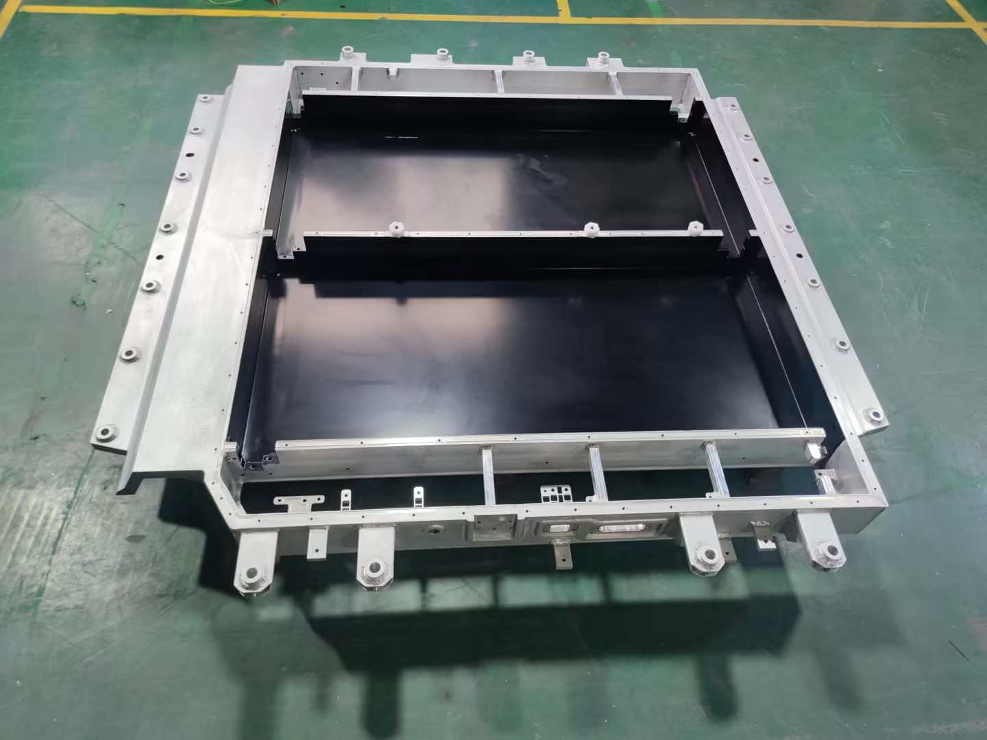
1- Battery tray / energy storage pack box aluminum alloy welding process characteristics
In the manufacturing of new energy liquid-cooled Pack boxes, battery trays and other products, liquid cooling channels and multi-cavity structures are typical complex design features (as shown in Figure 1). Such structures often include the following features:

Figure 1: Typical design of a battery tray
Three-dimensional space interlacing: the flow channels are distributed in a serpentine shape, with a large number of spatial turning points;
Multi-level connection: the main cavity and sub-cavity are connected by thin-walled partitions (thickness 2-3mm);
Miniaturization features: small flow channel cross-section size (the minimum wall thickness of the aluminum profile flow channel is 1.2mm) and poor welding accessibility.
2- Difficulty analysis of combining multiple welding technologies in battery tray manufacturing
In the practice of battery tray manufacturing, it is necessary to combine multiple welding technologies, such as the coordinated application of friction stir welding (FSW), cold metal transition welding (CMT), traditional melting welding (TIG/MIG) and other technologies. This combination aims to take into account lightweight, strength, sealing and production efficiency, but it also faces the following core difficulties:
a. The problem of coordinated heat input of multiple processes
Different welding technologies (such as FSW and laser welding) have large differences in heat input, which can easily cause material performance mutations and thermal deformation, and need to be solved by optimizing the welding sequence and parameter adjustment.
b. Equipment compatibility and efficiency bottleneck
Equipment switching is complex and parameter synchronization accuracy requirements are high. Modular workstation design and intelligent welding machines are required to improve collaborative efficiency and reduce cycle time.
c. Challenges of balancing sealing strength and cost
The risk of leakage at the intersection of multiple welds is high (accounting for 70% of defects), and redundant sealing + topology optimization design is required.

3-Engineering practice: Battery tray, energy storage liquid cooling PACK box multi-welding process coordination
a. Weld scar position planning
· Welding position optimization: In the product design stage, the rationality of the welding position should be fully considered to avoid weld scars appearing in key parts or areas that affect product functions. For example, adjust the gap between the front frame and the water nozzle to prevent weld scar interference; optimize the welding position of the water nozzle to reduce the impact on product performance.
· Matching with product structure: The welding position should match the product structure to ensure that the weld can withstand various loads and stresses during the use of the product. For example, in the liquid cooling plate project, the structural stability and reliability of the product are improved by rationally planning the welding position.
· Easy to operate and detect: The welding position should be convenient for operators to perform welding operations and subsequent quality inspections. For example, avoid welding in locations that are difficult to reach or have poor visibility to improve welding efficiency and quality.
b. Weld scar control
· Weld scar size: The size of the weld scar needs to be strictly controlled. Generally, the weld scar height is required to be within the range of 4/6mm, and the weld scar does not exceed the plane to ensure the appearance and assembly accuracy of the product. For example, in the liquid cooling plate project, the size of the weld scar was successfully controlled by adjusting the welding parameters and process, avoiding the impact of the weld scar on product performance and quality.
· Weld scar shape: The weld scar shape should be as regular as possible to avoid excessive melting or incomplete fusion. By optimizing welding parameters and operating techniques, the weld scar shape can be effectively improved and the weld quality can be improved.
· Grinding treatment: For the concave weld marks produced at the friction welding position, grinding treatment is used to ensure a smooth surface to meet the product appearance and performance requirements.
c. Welding sequence optimization
· Partition welding: For large products, the method of partition welding can effectively control the overall deformation. By dividing the product into several areas and welding them in sequence, the heat concentration during the welding process can be reduced and the risk of thermal deformation can be reduced.
· Step-by-step correction: During the welding process, the step-by-step correction method is used to adjust the welding deformation in time. By continuously measuring and correcting the deformation of the product during the welding process, the dimensional accuracy and shape of the final product are ensured to meet the design requirements.
· Optimize the welding path: Rationally plan the welding path to avoid repeated welding in the same area and reduce heat input. For example, in the liquid cooling plate project, the heat input during the welding process was reduced and the welding quality was improved by optimizing the welding path.
d. Deformation collaborative control
The liquid cooling plate undergoes thermal deformation during the welding process, resulting in a decrease in the dimensional accuracy of the product.
Optimization measures:
· Use partition welding and step-by-step correction methods to control the overall deformation.
· Optimize welding parameters, reduce current and voltage, and reduce heat input.
· Use fixtures to fix the product to reduce movement and deformation during welding.
Use symmetrical welding method to make welding heat evenly distributed.
We will regularly update you on technologies and information related to thermal design and lightweighting, sharing them for your reference. Thank you for your attention to Walmate.
CTC (Cell-to-Chassis) technology has attracted much attention because it can significantly improve the range and space efficiency of electric vehicles, but whether it can truly replace traditional battery technology is still controversial. The core bottleneck on the manufacturing side - the battery tray welding process - has become the key to determining the future of this technology: complex structural design, multi-material compatibility, and stringent thermal management requirements have put traditional welding technology to a huge test. Starting from the perspective of front-line engineers, combining industry trends and engineering practices, this article analyzes the potential and limitations of CTC technology, and explores how welding technology has become the "touchstone" of this technological revolution.
1-The "Ideal and Reality" of CTC Technology
CTC technology can theoretically reduce redundant structural parts and improve energy density by integrating the battery cell directly into the chassis, but the feasibility of its large-scale application is facing realistic challenges:
Car companies' radicalism and caution: Tesla, BYD and other leading companies have launched CTC solutions, but more manufacturers are still waiting and watching. Industry data shows that as of February 2025, CTC mass-produced models account for 15-20% of the world, and traditional CTP (Cell-to-Pack) technology is still the mainstream.
The "cost" of improved battery life: Although CTC can increase energy density by 15%-20%, the complexity of the chassis structure leads to an increase in manufacturing costs of 30%-50% (calculated by a consulting agency), and the balance between cost and benefit is not yet clear.
Maintenance economic controversy: The integrated design has caused the battery maintenance cost to soar. Insurance company data show that the replacement rate of battery assemblies after accidents of CTC models is as high as 70%, far higher than the 25% of traditional models.
These contradictions make the future of CTC technology full of variables. Whether the market can break through 20% depends on three major variables: the progress of Tesla Cybertruck mass production; whether the price war among Chinese automakers forces CTC to reduce costs; and the degree of compromise of European regulations on battery repairability. The level of welding technology on the manufacturing side will be the key to determining whether it can cross the gap between laboratory and mass production.
2-Three "life and death barriers" of welding process
For battery tray manufacturers, the implementation of CTC technology needs to overcome three core problems:
a. The game between "micron-level" precision and efficiency
Traditional welding processes can tolerate 0.5mm errors, but CTC trays need to carry more batteries, and the number of seams increases by more than 3 times, and most of them are distributed on curved and irregular parts. Tests by a manufacturer show that when the welding positioning error exceeds 0.15mm, the yield rate of battery cell assembly will drop sharply from 99% to 82%. What's more tricky is that the improvement in precision is often accompanied by a decrease in efficiency-although the accuracy of laser welding is high, the equipment cost is more than 5 times that of traditional welding.
b. The "water and fire" of mixed materials
In order to balance lightweight and strength, CTC trays often use a mixed structure of "aluminum alloy + carbon fiber + special steel". The difference in thermal expansion coefficients of different materials can be up to 20 times (such as aluminum 23μm/m·K vs. carbon fiber 0.8μm/m·K), which is easy to generate internal stress during welding and cause cracking. When a company tried to connect aluminum and carbon fiber, the crack rate of the weld was as high as 18%, far exceeding the industry's acceptable threshold of 3%.
c. "Invisible killer" of the heat-affected zone
High welding temperature may damage the insulating materials or sensor circuits around the battery cell. A car company once increased the self-discharge rate of the battery module by 50% due to improper control of welding heat input. Engineers must control the welding temperature fluctuation within ±15℃ within 0.1 seconds - this is equivalent to installing a "high-precision temperature brake" on the welding gun.
3-The way out: There is no silver bullet, only system innovation
Faced with these challenges, the industry is exploring three breakthrough paths:
a. "Cocktail therapy" of process combination
Laser arc hybrid welding: Combining the accuracy of laser welding with the advantages of arc welding penetration, the welding speed of aluminum alloy is increased by 40%;
Cold metal transition technology (CMT): Through precise heat input control, the area of heat affected zone is reduced by 60%;
Robot intelligent compensation system: Automatically adjust the welding gun path based on real-time weld scanning data, and increase the qualified rate of complex curved surface welding from 75% to 95%.
b. "Pre-compromise" on the material side
Some companies have begun to jointly develop "welding-friendly" composite materials with material suppliers. For example, the welding crack sensitivity of a domestic modified aluminum alloy (aluminum alloy material adjusted by physical, chemical or process means) has been reduced from level 7 to level 3 (according to ISO standards). Although it sacrifices 5% of the lightweight effect, it increases the welding yield to 98%.
4- Engineers’ new proposition: Finding certainty in uncertainty
a. The controversy over CTC technology is essentially a game between “system optimization” and “local limits”:
If the breakthrough speed of welding process is slower than the cost reduction expectations of car companies, CTC may become a niche technology;
If materials, processes, and testing technologies make breakthroughs in a coordinated manner, it is expected to usher in a new era of electric vehicle structural design.
b. For engineers, it is necessary to reconstruct capabilities from two dimensions:
Cross-domain knowledge integration: understand the sensitive threshold of electrochemical properties to welding heat input;
Agile response capability: A case study of a European supplier shows that the team that can complete the optimization of welding parameters of new alloy materials within a week has a 3-fold increase in the probability of obtaining orders.
CTC technology stands at the crossroads of “disruptive innovation” and “mass production trap”. It may not completely replace existing technology, but it is forcing the welding process to evolve towards higher precision, stronger compatibility, and more intelligent control. In this technology marathon, the real winner may not be the earliest car company, but the engineering team that turns “impossible welds” into “standardized interfaces” on the manufacturing side.
We will regularly update you on technologies and information related to thermal design and lightweighting, sharing them for your reference. Thank you for your attention to Walmate.
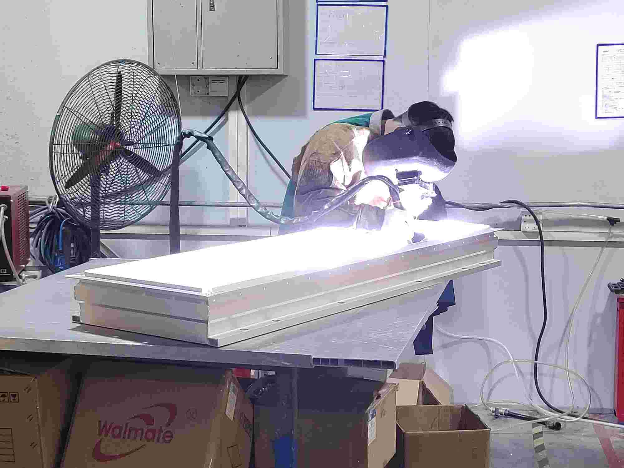
As CTP (Cell to Pack) technology completely subverts the traditional battery pack structure, the "role" of the battery tray has shifted from passive load-bearing to active integration. Welding technology has become the core of safety and performance. The requirements of lightweight (wall thickness is only 1.5mm), zero pore sealing, and multi-material (aluminum/copper/carbon fiber) integration have caused traditional welding to fall into the dilemma of deformation and defects. The industry is making breakthroughs through material innovation, intelligent quality inspection and process iteration. This article will analyze the disruptive challenges that CTP poses to welding and explore the technical path to high precision and high reliability.
1-Analysis of the changes in the structural design requirements of battery trays due to CTP technology
CTP (Cell to Pack) technology directly integrates the battery cells into the battery pack by eliminating the module structure in the traditional battery pack. This technological innovation puts forward all-round and multi-dimensional upgrade requirements for the structural design of the battery tray. The following is a specific analysis from the perspectives of materials, performance, process, integration, etc.:
(1) Comprehensive improvement of structural strength and shockproof performance
a. Mechanical bearing requirements after eliminating the module:
After CTP technology eliminates the module structure, the battery tray needs to directly bear the support, fixation and external force buffering functions of the battery cell. The traditional module disperses the mechanical load, while the CTP tray needs to absorb the expansion deformation of the battery cell during charging and discharging as a whole (for example, the expansion force of the square battery cell can reach 10-20kN), while resisting the vibration, extrusion and impact load during vehicle driving.
b. Material and structural optimization direction
· Dominance of high-strength aluminum alloy: Early steel was gradually replaced due to its heavy weight, and 6061-T6 became the mainstream. It has high specific strength and strong corrosion resistance, which can meet the dual requirements of lightweight and high rigidity.
· Composite structure design: For example, the "double-frame ring beam" structure of Leapmotor enhances local impact resistance through longitudinal and transverse beam compartments, while using extrusion technology to optimize material distribution and reduce redundant weight.
· Exploration of magnesium-aluminum alloy and carbon fiber: Magnesium-aluminum alloy is 30% lighter than traditional aluminum materials, and carbon fiber composite materials have both high strength and lightweight characteristics, but are currently only used in high-end models due to cost and process maturity.
(2) Requirements for integrated air tightness and thermal management
a. Sealing performance upgrade
After the module is removed, the internal coolant circulation and gas sealing of the battery pack are completely dependent on the tray, and welding defects (such as pores and cracks) may lead to leakage risks.

Figure 1-Battery tray air tightness test
b. Integration of thermal management functions
CTP trays need to integrate components such as liquid cooling plates and thermal conductive adhesives. For example, structural adhesives are used to fix the battery cells and transfer expansion stress, and polyurethane thermal conductive adhesives (thermal conductivity > 1.5 W/m·K) are used for heat conduction between battery cells and with liquid cooling tubes. The amount of adhesive used in a single PACK is more than 50% higher than that in traditional structures. Flow channels need to be designed inside the tray to optimize cooling efficiency while avoiding damage to the sealing caused by the heat affected zone of welding.
(3) Lightweighting and material innovation
a. Material selection trends
Aluminum alloy extrusion and die-casting process: extruded aluminum profiles are used for frame structures (such as Tesla's 4680 battery tray), and die-casting processes (such as integrated die-casting) simplify the welding process and reduce weight by 15%-20%.
Application of plastic composite materials: For example, glass fiber reinforced PA6 materials are used in non-load-bearing parts to further reduce weight, but the compatibility problem with the metal connection interface needs to be solved.
b. Lightweight design strategy
Topology optimization: Reduce redundant materials through CAE simulation and reduce the weight of the tray while ensuring strength.
Thin-wall and integrated: The wall thickness of the tray is reduced from 3mm to 1.5-2mm, and functional components such as BMS brackets and wiring harness channels are integrated to reduce the number of parts.
(4) Integration and modular design
a. High integration of functional components
CTP trays need to integrate modules such as battery management system (BMS), high-voltage connectors, and fireproof isolation layers.
b. Modular and compatible design
The welding production line needs to support mixed production of multiple models of trays, be able to achieve "one-click change of type", and be compatible with tray structures of different battery cell sizes (such as square and cylindrical).
2-Specific challenges of CTP technology innovation to welding process
CTP (Cell to Pack) technology has significantly improved space utilization and energy density, but it has also posed unprecedented challenges to welding process.
(1) The difficulty of controlling welding defects has increased sharply
a. Porosity and sealing challenges
After CTP technology eliminates the module, the battery tray needs to directly assume the sealing function. Welding pores (a common defect in aluminum alloy welding) will directly lead to the risk of coolant leakage or gas penetration.
b. Cracks and material compatibility
High zinc aluminum alloys (such as 7 series) are prone to cracks due to thermal stress during welding.
c. Gap and assembly error
The direct integration of multiple cells leads to an increase in the number of splicing points of the tray structure. The accumulation of assembly errors may cause the weld gap to exceed ±1mm.
(2) Process adaptation problems brought about by the upgrade of the material system
a. Welding challenges of lightweight materials
The CTP tray material has shifted from steel to aluminum alloy (6061-T6, 7075-T6), magnesium-aluminum alloy (30% weight reduction) and carbon fiber composite materials. Aluminum alloy welding needs to solve the problem of insufficient penetration caused by the difficult melting of the oxide film and high thermal conductivity.
b. Dissimilar material connection technology
When the tray integrates functional components such as liquid cooling plate (copper/aluminum) and fireproof layer (ceramic matrix composite material), brittle intermetallic compounds are prone to appear at the interface of dissimilar materials.
(3) Upgraded structural complexity and precision requirements
a. Deformation control of large-size thin-walled structures
The wall thickness of the CTP tray is reduced from 3mm to 1.5-2mm, and the sensitivity of welding thermal deformation increases sharply.
b. High-density solder joints and process efficiency
The number of solder joints on a single tray has increased from 2,000 in traditional modules to more than 5,000.

Figure 2- Battery tray welding
3-Upgrade of production process and quality control
CTP technology promotes the transformation of battery tray welding from "single process" to "multi-technology collaboration, intelligence, and greening". Manufacturers need to focus on three major directions:
Technology upgrade: break through the control of defects such as pores and cracks, and adapt to lightweight materials;
Intelligent transition: full process digitization and AI quality inspection to achieve high-precision production;
Ecological collaboration: jointly build technical standards with material suppliers, equipment suppliers, and OEMs.
We will regularly update you on technologies and information related to thermal design and lightweighting, sharing them for your reference. Thank you for your attention to Walmate.
On the path toward Exascale AI computing power, Huawei's CloudMatrix 384 Super Node and NVIDIA's GB200 NVL72 cluster have emerged as two globally prominent technological peaks. They not only represent different hardware integration capabilities but also profoundly reveal two fundamental philosophies for building supercomputing systems.
One is metaphorically described as a "sustained high fever," facing the ultimate thermal challenge of densely packed, steady-state heat dissipation from 384 chips operating at full throttle. The other is likened to "intermittent epileptic seizures," requiring the taming of intense, pulsed heat flows generated when 72 top-tier GPUs work in synchrony. These two different "maladies" ultimately lead to entirely distinct "prescriptions"—namely, thermal solutions—and provide us with a clear view of two core engineering philosophies: deterministic systems engineering versus agile ecosystem innovation. For every company in the supply chain involved, understanding this duel is key to defining their future role.
1-The Root of Core Differences – The "Malady" Determines the "Prescription"
From the outset of design, Huawei and NVIDIA embarked on different paths, directly shaping their distinct thermal source characteristics:
Table 1: Comparison of Thermal Source Characteristics Between Two Technical Approaches
The difference between this "sustained high fever" and "intermittent epileptic seizures" is by no means accidental. It reflects Huawei's choice as a challenger to focus on total system performance, pushing the limits of computing density within a single cabinet at all costs, while NVIDIA, as the leader, faces the task of building an ecosystem that can efficiently collaborate and be widely adopted while maintaining an absolute performance advantage per chip.
2- The Materialization of Engineering Philosophy – Two Liquid Cooling Paths
The two distinct design philosophies are most vividly embodied in their respective liquid cooling solutions, shaping the complete technology stack from the chip to the data center room.
a. Huawei: The Liquid Cooling Practice of Deterministic Systems Engineering
This is a top-down design philosophy born for system-level deterministic goals. Its core lies in treating thermal management as a crucial part of the infrastructure, achieving it through globally integrated, highly reliable engineering, rather than treating it merely as a supporting component.
Figure 1: Huawei Ascend 384 Super Node
· Chip-level Precision Engineering and Reliable Connection: To ensure efficient heat transfer from the chip to the cold plate, Huawei focuses on engineering optimization of interface materials. While public information shows its advanced patent reserves in this field (e.g., using high-sphericity silicon carbide fillers), its specific implementation within the super node remains undisclosed. It is certain that its solution inevitably pursues extremely low interfacial thermal resistance and long-term reliability to meet the "sustained high fever" challenge.
· System-level Redundancy and Intelligent Control: Adopts redundant designs, such as ring-shaped liquid supply, and develops in-house Liquid Cooling Thermal Management Units (TMUs) as the system's "central nervous system." This controller enables zero-second switching between pipelines and utilizes AI for failure prediction, ensuring the determinism and reliability of the thermal dissipation chain in a software-defined manner—a hallmark of its systems engineering thinking.
· Infrastructure Convergence ("Cooling-Power Integration"): At the cabinet level, the Liquid Distribution Unit (LDU) and the High-Voltage Power Distribution Unit (PDU) are physically integrated and managed uniformly. This "cooling-power integrated" design is the ultimate engineering response to the ultra-high power density per cabinet, simplifying deployment and improving energy efficiency (lowering PUE). It represents the physical manifestation of its deterministic design philosophy.
b. NVIDIA: The Liquid Cooling Framework of Agile Ecosystem Innovation
This is a design philosophy centered on the GPU, empowering the global ecosystem through the definition of open standards. Its core is to provide a validated "blueprint," lowering the application barrier for the entire industry and enabling efficient, flexible, and large-scale deployment.
· Chip-level Standardization and Reference Design (VRD): NVIDIA provides detailed thermal reference designs for its GPUs (e.g., the Blackwell series), explicitly defining the performance interfaces for the cold plate, including physical dimensions, Thermal Design Power (TDP), flow rate, and pressure drop. This essentially provides a "standard answer" for all cooling vendors, encapsulating complexity within standardized components and ensuring compatibility and a quality baseline for foundational parts.
Figure 2: NVIDIA Server Module and Micro-channel Cold Plate
· Ecosystem-level Collaboration and Solution Certification: Engages in deep collaboration with top thermal management and infrastructure vendors like Vertiv and Boyd to jointly develop and certify cabinet-level liquid cooling solutions. For instance, Vertiv's Tier 2 Ready cabinet solution is a pre-validated product developed based on NVIDIA's blueprint, enabling data center operators to rapidly obtain a plug-and-play liquid-cooled cluster as easily as procuring standard equipment.
· Digital Twin Enablement and Deployment Acceleration: Leveraging the NVIDIA Omniverse platform, it provides digital twin and simulation tools for data center liquid cooling systems. Customers can design, verify, and optimize cooling solutions in a virtual environment, significantly reducing the cost and risk of physical validation and achieving agility from design to deployment.
To understand these two paths more clearly, their core differences are compared below:
Table 2: Huawei Model vs. NVIDIA Model: Key Differences at a Glance
3- Historical Inspiration and Future Convergence
The competition between these two paths is not an isolated case in the history of technology. It is, in essence, another classic enactment of systemic integrated innovation versus platform-ecosystem innovation. Huawei resembles Apple during the Steve Jobs era, pursuing absolute control over the product experience from top to bottom. In contrast, NVIDIA is more like today's Google Android, driving the prosperity of an entire ecosystem by setting core standards (the Android system / GPU architecture).
For the industry, the future trend is not about one side completely replacing the other but likely involves a degree of convergence:
· In national or enterprise-level projects pursuing ultimate computing power, the allure of "Deterministic Systems Engineering" remains undiminished.
· In the vast commercial cloud computing market, "Agile Ecosystem Innovation" will continue to expand due to its speed and cost advantages.
· Sparks of ingenuity may emerge at the intersection: incorporating deeper customization and collaborative optimization within open ecological standards.
4- Conclusion
Therefore, the cooling debate between Huawei and NVIDIA is fundamentally a contest between two core competitive strengths in the AI era: one side pursues deterministic, extreme performance through the deep integration of systems engineering; the other drives agile industry innovation and rapid proliferation by building open standards and ecosystems. This duel delineates clear path choices for participants in the industrial chain: to act as a "spearhead force," deeply integrated and tackling specific system-level fortresses, or to serve as the "main force," integrating into the ecosystem to explore markets across the vast plains of standardization. Ultimately, victory lies not only in the technology itself but also in the insight into the logic of industrial evolution and a clear definition of one's position in the future blueprint.
We will regularly update you on technologies and information related to thermal design and lightweighting, sharing them for your reference. Thank you for your attention to Walmate.
When the "Large" Size of Battery Cells Becomes a Consensus, the "Strength" of the Pack Becomes the New Battleground
The energy storage industry is entering an era of leapfrogging battery cell capacities, with the shift from 280Ah towards 500Ah+ already underway. While the industry focuses on the "largeness" of cells, the "strength" of the Pack—specifically its mechanical structure's load-bearing and safety mitigation capabilities—is becoming the new competitive focus. Regardless of the evolution in cell chemistry and capacity, the resulting expansion forces, thermal runaway energy, and mechanical loads ultimately must be borne by the Pack's lower enclosure, its mechanical foundation.
From a structural design perspective, this article explores how the Pack lower enclosure can address differentiated mechanical and thermal management demands amidst diverging cell technology pathways, and build sustainably adaptable engineering capabilities.
1- Mechanical Analysis of Three Major Technology Paths: The Triangular Challenge of Load, Heat, and Space
The increase in cell capacity directly alters the boundary conditions for Pack system design. As the "skeleton" and "skin" of the system, the lower enclosure must re-address three fundamental questions:
a. Mechanical Analysis for the 587Ah (High-Integration Path)
Core Demand: Achieving energy density ≥6MWh within a standard 20-foot container has spurred ultra-compact layouts like "4 columns, 8 clusters in total."
Lower Enclosure Challenges:
· Structural Load-Bearing Optimization: With increased overall mass but reduced support points, the enclosure must optimize load transfer paths, balancing overall stiffness with local strength in critical areas to ensure structural stability during transportation and operation.
· Integration of Thermal Management Structure: The liquid cooling system is deeply integrated with the enclosure's base plate and support structures, serving both as the thermal management core and participating in overall load-bearing. The design must ensure the long-term reliability of cooling seals under sustained structural loads and thermal cycling.
Simulation of Energy Storage Pack Lower Enclosure
· Precise Spatial Coordination: The enclosure must allocate reasonable clearances within the limited space for cell expansion, thermal displacement of electrical connections, fire suppression piping, etc., enabling the reliable coexistence of all subsystems within the compact layout.
b. Thermo-Mechanical and Structural Response Analysis for the 684Ah (Ultra-Large Capacity Path)
Core Demand: Minimizing cost per Wh by maximizing single-cell capacity, which introduces physical centralization effects.
Lower Enclosure Challenges:
· "Focal Point" Effect of Expansion Force: The expansion force of a single cell does not increase linearly with capacity but nearly exponentially. The internal frame of the enclosure requires a more robust and uniform "restraint system" to distribute the concentrated expansion stress across the entire structure, avoiding local plastic deformation.
· "Uniformity" Dilemma in Thermal Management: Larger heat-generating bodies require more efficient heat conduction paths. The material, thickness of the enclosure's base plate, and the design of the contact interface with the cell bottom (such as the compression ratio setting for thermal pads) become critically important. During thermal runaway, the larger energy release places higher demands on the directional venting capability of pressure relief channels and the flame-retardant duration of internal fire barriers.
· Structural Response to Concentrated Weight: Heavier individual cells alter the overall vibration modes of the Pack. The lower enclosure requires renewed fatigue simulation to prevent resonance at specific frequencies leading to fastener loosening or structural cracks.
c. Manufacturing Adaptability Explanation for the 392Ah (Robust Transition Path)
Core Demand: Focuses on balancing performance, cost, and delivery efficiency, providing a thoroughly validated solution to the market.
Lower Enclosure Challenges:
· Stable Realization of Mature Solutions: Ensuring product consistency through strict process control based on a verified design and manufacturing system, supporting rapid and stable mass production schedules.
· Deep Supply Chain Collaboration: Leveraging an established supply system to continuously enhance the product's comprehensive cost competitiveness through material selection, process optimization, and scaled procurement.
2- Engineering Thinking to Address Divergence
Confronted with multiple technology pathways, lower enclosure suppliers cannot rebuild their technical systems for each path. The real solution lies in platform-based, precise response—efficiently adapting to different requirements through scalable, modular design.
a. Focusing on Common Physical Principles and Collaborative Models
Cell iteration follows stable physical laws. We have established a collaborative evaluation process based on core parameters, integrating materials and structural data to rapidly assess the feasibility of new cells. This enables early identification of matching risks, helping to converge design directions and reduce late-stage iterations.
587Ah Energy Storage Battery Pack Lower Chassis
b. Building a Flexible System of "Standardized Interfaces + Configurable Modules"
To address the customization demands arising from technological divergence, we have established a design system with clearly defined interface standardization and internally configurable modules:
· Unified External Interfaces: Installation positioning to the energy storage container, electrical penetration interfaces, cooling system connection points, etc., all strictly adhere to common industry specifications, ensuring compatibility and assembly consistency at the system level.
· Configurable Internal Structure: We offer a series of internal support components and thermal management integration solutions that can be flexibly combined according to cell dimensions and layout.
· Thermal Management Integration Module: The thermal management module adopts a modular design, focusing on optimizing temperature rise control and cell temperature uniformity. It can flexibly adapt to the thermal management needs of different technology paths.
c. Implementing Flexible Production Lines with "Design for Manufacturability"
To match the diversity of technology paths, our manufacturing system is organized around an extensible base platform and modular assembly:
· Base Enclosure Platform Manufacturing: Ensures the precision and consistency of the main structure, providing a reliable carrier for different configurations.
· Modular Assembly Units: Supports flexible selection and assembly of corresponding internal support and thermal management modules based on cell size and layout. Through this setup, we can efficiently switch production for products of different technology paths on the same line, assisting customers in managing supply chain and delivery challenges posed by parallel multi-path development.
3- Redefining the Value of the Lower Enclosure: From Passive Bearing to Active Enablement
The lower enclosure is transitioning from a passive container to a critical system-enabling component, directly impacting safety, energy density, and total lifecycle cost:
a. Safety-Critical Load-Bearing Structure: By providing reliable structural channels and mounting foundations for system-level pressure relief and fire barriers, it works in concert with thermal runaway propagation control to build multi-tiered safety protection.
b. Energy Density Enabler: Lightweight, high-strength design reduces its own weight and spatial footprint, reserving more performance margin for the battery cells and cooling system.
c. Long-Term Reliability Assurance: Structural integrity and fatigue endurance design support the system in withstanding continuous challenges like long-term cycling and transportation vibrations.
4- Conclusion: Building a Bridge Between Diverging Upstream and a Determined Downstream
As battery cell technology evolves, energy storage systems relentlessly pursue safety, high density, and low cost. The lower enclosure must provide a reliable and adaptable foundational support, utilizing modularity and flexible manufacturing to accommodate different technology pathways. Industry competition is shifting towards system-level engineering, where the Pack enclosure serves as a pivotal link.
We will regularly update you on technologies and information related to thermal design and lightweighting, sharing them for your reference. Thank you for your attention to Walmate.
Over the decades of data center development, air cooling technology has consistently been the mainstream choice. However, the launch of NVIDIA's GB200 series products is decisively shattering this equilibrium. As computational density reaches new heights, traditional cooling methods can no longer meet the demands. Liquid cooling technology is now formally stepping from behind the scenes to center stage, becoming the critical infrastructure supporting AI computing power.
1- Fundamental Shifts on the Demand Side
a. Power Density Breaks the Critical Point
The power density of a GB200 NVL72 rack is projected to exceed 30 kW per rack, a figure far beyond the 15-20 kW thermal dissipation limit of traditional air cooling. This signifies:
· An Inevitable Choice of Technology Path: Liquid cooling transitions from "worth considering" to the "only viable option."
· A Qualitative Change in Market Scope: Each GB200 deployment represents a definitive demand for liquid cooling.
· A Significant Increase in Value: The liquid cooling system for a single rack reaches a value level of several hundred thousand RMB.
b. Reliability Requirements Are Upgraded
As the compute density per rack increases, the business value it carries grows exponentially. The reliability of the liquid cooling system is directly linked to:
· Business Continuity: A single cooling failure could lead to computing power losses worth millions.
· System Lifespan: For every 10°C temperature increase, the lifespan of electronic components is halved.
· Performance Stability: Cooling efficiency directly impacts whether chips can sustain peak performance.
2- Comprehensive Enhancement of Technical Requirements
a. Leap in Cooling Efficiency Demands
The GB200 places unprecedented demands on the cooling system:
· Doubling of Heat Transfer Performance: The thermal conductivity of cooling plates needs to be 3-5 times that of traditional solutions.
· Order-of-Magnitude Reduction in Contact Thermal Resistance: Requires contact thermal resistance to be reduced by one order of magnitude.
Figure 1 - Microchannel cold plate
b. Flow Rate Precision Control
· Requires flow control accuracy within ±1%.
· Supports dynamic flow rate adjustment to adapt to different load conditions.
c. Temperature Uniformity
· Temperature difference across the chip surface must be controlled within 5°C.
· Prevents local hotspots from affecting system stability.
3- Leap in System Integration Complexity
Liquid cooling systems have evolved from simple component supply to complex system engineering:
a. Traditional Model:
· Provision of standardized cooling plates.
· Simple piping connections.
· Basic monitoring functionality.
b. The GB200 Era:
· Rack-level liquid cooling architecture design.
· Intelligent flow distribution systems.
· Real-time health status monitoring.
· Predictive maintenance capabilities.
Figure 2 - NVIDIA GB200 cabinet
4- Comprehensive Elevation of Competitive Barriers
In the new market environment, companies must now clear significantly higher thresholds:
a. Technical Barriers
Liquid cooling companies must break through the limitations of single disciplines and build a comprehensive, cross-disciplinary technological system. The deep integration of multi-disciplinary technologies such as microchannel design, materials science, and fluid dynamics has become the basic entry requirement. Furthermore, capabilities in chip-level thermal simulation and optimization truly test a company's profound technical accumulation. This is no longer merely a matter of simple process improvement, but a systemic engineering challenge requiring long-term R&D investment.
b. Certification Barriers
The industry certification system is becoming increasingly stringent. Companies must not only pass the rigorous reliability tests mandated by server manufacturers but also obtain technical certification from the original chip manufacturers. This dual certification requirement not only validates a product's technical performance but also rigorously tests a company's quality management systems and its ability to ensure stable, continuous supply. It has become an essential passport for entering the core supply chain.
c. Service Barriers
As liquid cooling systems are upgraded to core subsystems, service capability has become a critical competitive factor. Companies must establish nationwide rapid-response networks and build professional, 24/7 operational and maintenance systems. This service capability demands not just the timeliness of technical support but also comprehensive end-to-end service solutions encompassing preventative maintenance and emergency response, truly positioning the company as a trustworthy partner for its clients.
We will regularly update you on technologies and information related to thermal design and lightweighting, sharing them for your reference. Thank you for your attention to Walmate.
In the history of computing architecture evolution, certain moments do not arrive silently. The launch of NVIDIA's GB200 NVL72 is one such moment—it is not merely a new product, but a complete reconceptualization of the server itself.
For three decades, a "server" has consistently meant a standardized chassis unit: containing a motherboard, CPU, memory, storage drives, and expansion cards, interconnected via industry-standard interfaces. We measure it in "U"s, rack and stack it in cabinets, and connect to it over networks. However, the emergence of the GB200 NVL72 is fundamentally dissolving this long-standing definition at its core.
Its essence is no longer "a server," but rather a "computer" that takes the form of an entire rack. Traditional server components are deconstructed and then reintegrated on a grander scale—via NVLink-C2C, liquid cooling, and rack-scale power management—into an indivisible computational whole. This is no simple upgrade; it is a profound paradigm shift.
1- What is a "Server"? The Answer to This Question is Changing
For three decades, our understanding of a server has been a standardized chassis: inside resides a motherboard, CPU, memory, storage drives, and expansion cards, all adhering to industry standards, allowing for arbitrary replacement and upgrade.
But the change brought by the GB200 is fundamental:
· The computational heart is no longer discrete CPUs and GPUs, but the GB200 Superchip—a holistic entity deeply integrating a CPU and a GPU.
· Interconnect no longer relies on standard PCIe slots, but on customized NVLink backplanes.
· Cooling is no longer an optional accessory, but an integrated liquid cooling system.
· The fundamental unit of deployment has shifted from the "chassis" to the "rack."
The various components of the traditional server have been "torn apart," only to be reassembled and integrated anew at the larger scale of the rack. This is not evolution; it is re-architecture.
Table 1 - Reshaping the Physical Architecture: From "Chassis" to "Rack"
2- The Three Pillars of "Rack-Scale Architecture"
Traditional server design involves balancing trade-offs within a sealed chassis. In contrast, the rack-scale architecture represented by the GB200 approaches cooling, interconnect, power, and management as a complete system, designed holistically at a top level in a new dimension. This is no longer about stacking components, but about deep, system-level integration. This relies on the synergistic innovation of three core pillars working together.
Pillar One: From "Network Interconnect" to "Backplane Bus"
In traditional data centers, servers are independent nodes communicating over a network (like Ethernet). Within the GB200 NVL72, however, the NVLink Fabric functionally replaces the traditional motherboard bus, becoming the "skeleton" connecting all computing units. This shift enables the 72 GPUs in the rack to work in concert like a single, massive GPU, achieving orders-of-magnitude improvements in communication bandwidth and latency.
Pillar Two: Cooling Evolves from "Supporting Facility" to "Core Subsystem"
When computational density progresses from tens of kilowatts per rack to hundreds of kilowatts, traditional air cooling becomes ineffective. Liquid cooling is no longer an optional "supporting facility"; it has become a core subsystem on par with computing and interconnect. Its design directly determines the overall system's performance output and operational stability, making it the key factor in transitioning from "usable" to "high-performance."
Pillar Three: The "Centralization and Re-architecting" of Management and Power
The GB200 adopts rack-level centralized power supply and management. This is not merely about pursuing higher power conversion efficiency, but also a redefinition of system coupling. It brings benefits like simplified cabling and unified management visibility. However, it also expands the potential failure domain from a single server to the entire rack, placing new paradigm-level demands on operational maintenance.
3- The Restructuring and Shift of the Value Chain
The influence of the "rack-scale architecture" represented by the GB200 extends far beyond technology itself, clearly outlining a new industry value chain curve. Traditional value distribution is being disrupted, while new high-value strongholds are quietly forming around system-level integration and hardware-software co-design.
Server Vendors: Strategic Transformation from 'Definers' to 'Integrators'
Traditional server giants, like Dell and HPE, are facing a migration of their core value. The capabilities they once thrived on—motherboard design, system optimization, and standardized manufacturing—are seeing their importance diminish within highly customized, pre-integrated systems like the GB200.
However, new strategic opportunities lie within this crisis:
· Value Moving Upstream: The competitive focus shifts from internal server design to rack-level liquid cooling, power efficiency, and structural layout.
· Value Extending Outward: Core competitiveness extends from hardware manufacturing to professional services for large-scale deployment, cross-platform operational management, and integration capabilities with enterprise IT environments.
This signifies that the role of server vendors is transforming from being "definers" of standard products to becoming "advanced integrators and enablers" of complex systems.
Cloud Vendors' 'Strategic Procurement': Balancing Dependency and Autonomy
For hyperscale cloud vendors, the GB200 is both a strategic necessity and a strategic warning.
· Short-term Tactic: As the ultimate benchmark for computing power, procuring GB200 is an inevitable choice to meet market demand for top-tier AI compute.
· Long-term Strategy: To mitigate supply chain risks and technology lock-in, developing in-house AI chips (like TPU, Trainium, Inferentia) has become a core strategy crucial for future autonomy.
The actions of cloud vendors vividly reflect the complex trade-offs between efficiency and autonomy, and between short-term market needs and long-term control.
The Evolution of End-User Decision-Making: From Evaluating 'Components' to Assessing 'Output'
For end-user technical decision-makers (CTOs, Technical VPs), the procurement evaluation paradigm is undergoing a fundamental shift.
Traditional Procurement Checklist:
· CPU core count and clock speed
· GPU model and quantity
· Memory and storage capacity and speed
Current Strategic Considerations:
· Efficiency Metrics: Performance per watt, total model training time
· Total Cost of Ownership (TCO): Comprehensive cost including hardware, energy consumption, maintenance, and manpower
· Business Agility: Time cycle from deployment to productive output
This shift marks a critical evolution in corporate technology procurement from a cost-center mindset to a productivity-investment mindset.
The GB200 has redefined the compute unit—from the "server" to the "rack." This is not merely a performance upgrade, but a complete paradigm shift in architecture. The pursuit of efficiency has transcended mere component stacking, and the industry value chain is being restructured. In this transformation, the only certainty is this: adapt to it, or be left behind.
A new computational epoch has begun.
We will regularly update you on technologies and information related to thermal design and lightweighting, sharing them for your reference. Thank you for your attention to Walmate.

When your device has multiple core hot spots that are independent of each other, have varying power consumption, or require isolated cooling, traditional single-channel cold plates become inadequate. Multi-loop copper tube embedded cold plates are the key to overcoming this challenge.
1-Why Choose Multi-Loop? Three Scenarios That Address Key Pain Points
a.Isolate Thermal Interference to Ensure Core Unit Performance
When components such as IGBTs and diodes, or CPUs and GPUs, are densely arranged, a single flow channel can cause thermal "crosstalk," forcing low-temperature components to operate in high-temperature environments. The multi-loop design acts like a "dedicated air conditioner" for each component, completely eliminating thermal interference and ensuring each unit operates within its optimal temperature range, thereby enhancing overall system performance and stability.
b. Achieve System Redundancy for High-Reliability Architecture
In fields with extremely high reliability requirements, such as servers and communication base stations, the failure of a single cooling loop can lead to system downtime. The multi-loop design enables the construction of an "N+1" redundant cooling system. If one loop fails unexpectedly, the remaining loops can still provide basic cooling capacity, buying valuable time for system maintenance. This serves as the cornerstone of high-availability design.
c. Address Irregular Layouts and Differentiated Cooling Needs
For irregularly arranged heat sources, a single flow channel struggles to achieve uniform cooling. The multi-loop solution supports "tailored designs," allowing you to customize the path of each copper tube flexibly based on the actual shape and layout of the heat sources. This ensures optimal flow paths precisely covering every hot spot. Additionally, high-power consumption components can be assigned high-flow loops, while low-power consumption components can be assigned low-flow loops, achieving the optimal allocation of cooling resources.
Figure 1: Multi-loop embedded copper tube cold plate
2-The Core of Design and Manufacturing: How to Balance Performance and Reliability in a Compact Space?
In multi-loop designs, the spacing between flow channels is critical to success.
a. Thermal Bottom Line: Preventing "Thermal Short Circuits"
If the spacing between adjacent flow channels is too narrow, even with independent channels, heat can rapidly conduct through the aluminum substrate in between, significantly compromising the isolation effect. Through simulation and testing, we have established a fundamental spacing principle of ≥1.5 times the tube diameter to ensure thermal independence.
b. Structural Red Line: Upholding the "Pressure-Bearing Lifeline"
The aluminum substrate between flow channels is a weak point for withstanding internal pressure. Excessively narrow spacing can lead to insufficient rib strength, posing a risk of tearing under pressure impact. Through mechanical stress simulation, we ensure that the stress between flow channels remains well below the material's yield limit under all operating conditions, fundamentally eliminating the risk of "plate rupture."
Figure 2: Embedded copper tube cold plate
c. Process Limits: Ensuring "Precision Manufacturing"
Narrow spacing poses a significant challenge for milling cutters. Based on extensive manufacturing experience, we correlate spacing with cutter diameter to ensure efficient machining while achieving smooth and flat channel walls. This lays the foundation for the subsequent tight nesting of copper tubes and low thermal resistance bonding.
3- Key Engineering Implementation Considerations
A successful multi-loop design requires attention to the following key aspects:
a. Collaborative Design
It is recommended to integrate thermal and mechanical design from the conceptual stage, taking into account flow channel layout, structural strength, and process capabilities to avoid subsequent design changes.
b. Process Control
• Utilize high-precision CNC milling for channels to ensure slot width tolerance and surface quality.
• Employ mandrel bending technology for copper tubes to maintain post-bending通畅性 and uniform wall thickness.
• Implement reliable nesting and fixation processes to prevent copper tube displacement under vibration conditions.
c. Verification Testing
A comprehensive testing system includes:
• 100% air tightness testing
• Flow rate–pressure drop characteristic testing
• Thermal resistance performance verification
• Burst pressure testing
In summary, multi-loop copper tube embedded cold plates are a powerful solution for addressing complex multi-heat source cooling challenges. The key to success lies in a deep understanding of their design logic and finding the optimal balance between performance and reliability.
We will regularly update you on technologies and information related to thermal design and lightweighting, sharing them for your reference. Thank you for your attention to Walmate.

1-Copper Tube Pre-treatment (Bending and Flattening)
Objective: To shape straight round copper tubes into flattened forms that exactly match the designed flow paths.
a. Material Selection: Why Oxygen-Free Copper?
Oxygen-free copper (C1220) has a purity of up to 99.9% and is free of grain boundary oxides, giving it excellent ductility, making it as malleable as dough. It is less prone to cracking or micro-cracking during bending and flattening, ensuring subsequent reliability.
b. Bending Radius: The Safety Bottom Line
The minimum bending radius must be ≥ 1.5 times the tube diameter—this is an iron rule. If this value is exceeded, the outer wall of the copper tube will be over-stretched, leading to thinning or even rupture. Using a mandrel bending machine is key to preventing wrinkling on the inner side.
c. Flattening: A Precise "Slimming" Process
Flattening is not simply about crushing the tube; it involves controlled plastic deformation through precision molds. The height of the flow channel after flattening must not be less than 30% of the original inner diameter. The core goal is to ensure uniform wall thickness after flattening, avoiding local dead folds or excessive thinning, as such defects would become potential leakage points in the future.
Figure 1: Heat Pipe Bending
d. Process Decision: Bend First or Flatten First?
It must be "bend first, then flatten." Bending round tubes is a mature and controllable process. If flattened first, the flattened tube can hardly undergo small-radius, high-quality bending, and the inner wall of the flow channel would be severely deformed, causing a sharp increase in flow resistance.
2-Substrate Processing (Precision Groove Milling)
Objective: To machine precisely dimensioned "tracks" on the aluminum substrate for embedding the copper tubes.
Figure 2: Embedded Copper Tube
a. Groove Width Design: Interference Fit
The groove width must be designed slightly smaller than the width of the flattened copper tube (typically by 0.05-0.1 mm) to form an "interference fit." This utilizes frictional force to tightly "grip" the copper tube, which is the foundation for initial fixation and reducing contact thermal resistance.
b. Groove Depth Control: Skiving Allowance
The groove depth determines the height by which the copper tube protrudes above the substrate surface after embedding. This height constitutes the machining allowance for the subsequent skiving process. The consistency of the groove depth directly affects the uniformity of the final remaining wall thickness of the copper tube.
c. Tooling and "Tool Chatter"
When milling narrow and deep grooves, an excessively large length-to-diameter ratio of the milling cutter can easily cause "chatter." This leads to rough groove walls and dimensional inaccuracies. Therefore, the flow channel spacing cannot be too small; sufficient space must be reserved for tool strength and rigidity.
d. Cleanliness: The Invisible Quality Factor
After groove milling, aluminum chips and oil stains must be 100% removed. Any residue will form a thermal barrier between the copper tube and the aluminum substrate, significantly increasing the contact thermal resistance and causing a substantial degradation in thermal performance.
3-Nesting and Fixation
Objective: To precisely embed the formed copper tube into the substrate groove and form a stable bond.
a. Interference Fit: The Primary Fixation Force
Relying on precise dimensional design, an external force from a press is used to "squeeze" the copper tube into the slightly narrower groove. The elastic restoring force of the material itself generates a significant normal pressure, which is the primary source of the fixation force.
Figure 3: Heat Pipe Securing
b. Auxiliary Fixation: Preventing the "Seesaw Effect"
Relying solely on the interference fit, the ends of the copper tube may lift under thermal stress. Auxiliary fixation is required: micro-spot welding (high strength, requires thermal control) or high thermal conductivity epoxy resin (low stress, but has aging risks).
c. The Enemy of Interface Thermal Resistance
Air between the copper tube and the aluminum groove is a poor conductor of heat and is the main source of interface thermal resistance. High thermal conductivity paste or welding can fill the microscopic gaps, replacing the air and significantly reducing the thermal resistance.
d. Galvanic Corrosion Warning
Aluminum and copper can form a galvanic cell in the presence of an electrolyte, where aluminum, acting as the anode, will corrode. It is crucial to ensure the cooling system's integrity and use deionized water/anti-corrosion coolant to eliminate the corrosion path at the system level.
4-Surface Finishing (Skiving vs. Deep Burial)
Objective: To form the final cooling surface, which can be used for mounting chips, characterized by high flatness and low thermal resistance.
copper tubed cold plate from Walmate
a. Skiving Process: The Performance King
This process uses ultra-hard cutting tools to simultaneously cut both copper and aluminum, creating a perfectly co-planar and flush surface. This allows the heat source to achieve direct, large-area contact with the highly thermally conductive copper tube, resulting in the lowest possible thermal resistance.
b. Deep Buried Tube Process: The Reliability Guardian
This process involves embedding round copper tubes and filling the gaps with high thermal conductivity epoxy resin. The copper tubes retain their circular shape, offering greater pressure-bearing capacity. The filler material provides additional protection and stress buffering, leading to higher reliability, although the thermal resistance is slightly higher than that achieved by skiving.
c. Final Wall Thickness: The Lifeline
The core control objective of the skiving process is the final remaining wall thickness of the copper tube. A balance must be struck between performance (requiring thin walls) and reliability/prevention of cutting through (requiring thick walls). This thickness is typically controlled within the golden range of 0.15-0.3 mm.
d. Flatness: The Guarantee of Contact
Regardless of the process used, the flatness of the mounting surface (typically required to be <0.1 mm) is a mandatory specification. Micron-level variations must be filled with thermal grease. Poor flatness will lead to a sharp increase in contact thermal resistance, resulting in cooling failure.
We will regularly update you on technologies and information related to thermal design and lightweighting, sharing them for your reference. Thank you for your attention to Walmate.
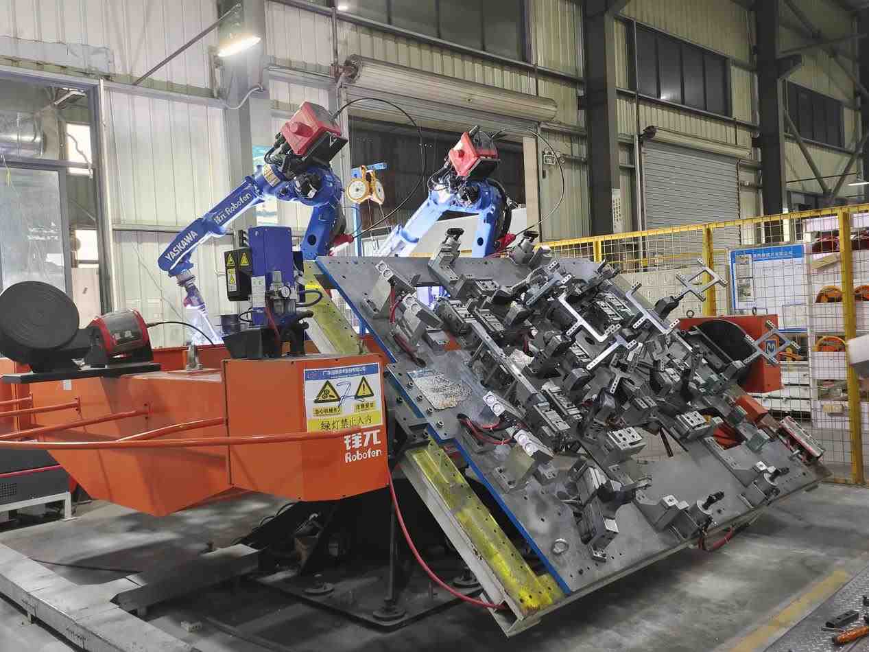
To enhance the range and capacity of electric vehicles, Power Battery Packs are transitioning from single-layer layouts to Multi-layer Stacking Structures. This shift significantly improves Energy Density, while also introducing entirely new structural challenges. This article will explore three aspects: core challenges, mainstream solutions, and future technological directions.
1-Core Challenges: Mechanical Challenges of Multi-layer Stacking
Expanding Battery Packs from a single layer to Multiple Layers is far from simple stacking. It reshapes the internal mechanical environment and external Load Paths, presenting four core challenges:
a.Vertical Load Surge and Material Creep Risk
・In Multi-layer Structures, the weight of Cells, Modules, and Structural Components accumulates layer by layer. The Static Compressive Load borne by the bottom layer is significantly higher than that of the top layer.
・This sustained High-Stress environment poses severe tests to the Long-Term Performance of materials, particularly Anti-Creep Performance (the slow Plastic Deformation of materials under Constant Stress over time).
・If Interlayer Supports or Cell Fixation Components undergo Creep, it may lead to Preload Relaxation, affecting Cell Cycle Life and Interface Contact Stability. Therefore, identifying materials that combine Lightweight properties with excellent Anti-Creep Characteristics is crucial.
b.Expansion ForceStacking Effect and Structural Stability
・Lithium-Ion Batteries experience a "Breathing Effect" during Charging and Discharging due to Volume Changes in Electrode Materials, leading to Cell Expansion. In Multi-layer Stacking Structures, Expansion Forces accumulate layer by layer, causing the bottom-layer Modules to withstand enormous pressure.
・This Cyclic Stress can easily trigger Casing Bulging, Seal Failure, Structural Component Compression, Cell Short Circuits, and accelerated Battery Performance Degradation. Effective control requires Built-in Sensors for Real-Time Monitoring combined with Digital Simulation to guide Structural Optimization Design.
c.Core Contradiction Between Space Utilization and Energy Density
・Addressing Gravity and Expansion Forces requires Reinforced Structures (such as adding Crossbeams or thickening Plates), but this occupies valuable space and increases weight, conflicting with the core goals of improving Volumetric Energy Density and Gravimetric Energy Density.
・The solution lies in Structural Optimization and the application of Efficient Materials, driving the transition of Battery Packs towards Multi-Material Hybrid Designs.
d.Collision LoadTransfer Path and Safety Redundancy Upgrade
・The Increased Height of Battery Packs intensifies Mechanical Loads during Side Impacts or Bottom Impacts; the Heightened Structure amplifies the Lever Effect, placing higher demands on Connection Point Strength and the Battery Pack's Own Stiffness.
・The use of Impact-Resistant Materials and Integrated Design is necessary to optimize Force Transfer and Energy Absorption, ensuring Cell Safety under Extreme Conditions, thereby promoting the development of Cell-to-Body Integration (CTC) technology, making the Battery Pack an integral part of the Vehicle Body Structure.
2- Comparative Analysis of Mainstream Structural Solutions
To address these challenges, the industry has explored various innovative solutions:
a.One-Piece Die-Cast Tray
・Advantages: High Integration, reduced Part Count, improved Overall Stiffness, Consistency, and Sealing. The Process supports Complex Geometries, facilitating the integration of Cooling, Reinforcing Ribs, and Mounting Points. The Monolithic Structure helps manage Complex Stresses.
・Challenges: Integral Die-Casting of Multi-Layer Frames imposes extremely high demands on Equipment, Molds, and Processes, making it costly. Post-Collision Repair is difficult or impossible. The Monolithic Rigid Structure may lack the Flexibility to manage Differential Expansion Forces between Layers.
b.Multi-Level Frame Modular
・Advantages: Flexible Design and Manufacturing, facilitating Production, Maintenance, and Replacement. Naturally suited for Multi-Material Hybrid Designs, allowing optimization of Performance and Cost for different Levels. Drawing on the "Quasi-Isotropic Lamination" concept of Composite Materials to optimize Overall Mechanical Response and disperse Stress.
・Challenges: Numerous Components and Connectors, Complex Assembly, Accumulated Tolerances affecting Precision and Preload. Numerous Connection Interfaces (Bolts, Rivets) are Potential Failure Points and add weight.
c.Hybrid Material Sandwich Structure
・Advantages: Excellent Lightweight Efficiency and extremely high Specific Stiffness (High-Strength Panels + Lightweight Core Materials such as Foam/Aluminum Honeycomb). Strong Bending Resistance, with Core Materials offering both Thermal Insulation and Energy Absorption Characteristics, enhancing Thermal Safety and Collision Safety. Aligns with the trend of Multi-Functional Integration.
・Challenges: Complex Manufacturing Process and high cost. The Interfacial Bond Strength and Long-Term Durability between Panels and Core Materials are critical. Core Materials must possess excellent Compressive Creep Resistance.
d.Bionic Honeycomb Structure
・Advantages: Theoretically an ideal Bionic Design (mimicking the HexagonalHoneycomb) for achieving Ultimate Lightweight, High Stiffness, and Compressive Strength. Provides Uniform Support with strong Impact Energy Absorption Capability.
・Challenges: Extremely complex Manufacturing and high cost, with significant Integration Difficulty with Cooling Systems etc. Currently primarily in the Frontier Research stage, requiring more time for large-scale Commercial Application.
3- Key Technological Breakthrough Directions
Future key breakthroughs in solving the Design Challenges of Multi-layer Stacking lie in:
a.Material and Process Innovation for Lightweight and Stiffness Balance
・Materials: Continuous optimization of CFRP, Aluminum Alloys, Magnesium Alloys; development of new Multifunctional Polymers and Composite Materials combining Low Creep, High Insulation, Good Thermal Conductivity, and Easy Processability.
・Processes: Development of Advanced Connection Technologies (Resistance Spot Welding, Laser Welding, Ultrasonic Welding) to achieve reliable, lightweight Multi-Material Connections.
b. Adaptive Management of Expansion Forces
Shifting the approach from "Rigid Resistance" to "Flexible Adaptation", creating Dynamic Response Systems to keep Cells in the Optimal Stress Environment throughout their Lifecycle.
Figure 1: Robotic laser welding of battery trays
c.Interlayer Connection and Integration Revolution
・Connection Technologies: Evolution from BoltMechanical Connections to Structural AdhesiveBonding and Advanced Welding for more uniform Stress Distribution, Good Sealing, and Fatigue Resistance.
・Ultimate Integration: CTC/CTB (Cell-to-Chassis/Body) is an important future direction for Battery PackIntegration. By eliminating Independent Housings and directly integrating Cells or Modules into the Chassis, the Multi-layer Stacking itself becomes a Vehicle Body Structural Component (such as Crossbeams or Floors), fundamentally solving Space Constraints and maximizing Battery Structural Functionality. Achieving this technology requires Deep Collaboration across multiple fields including Batteries, Structures, Thermal Management, and Safety, representing the Ultimate Form of the "Structure as Function" concept.
Figure 2: EV Battery tray
Multi-layer Stacking is an inevitable choice for increasing BatteryEnergy Density, but it also brings enormous challenges in Structure, Expansion Forces, and Safety. The solution lies in Material Innovation, Bionic Structural Optimization, and Intelligent Management of Expansion Forces. Ultimately, Battery Packs will Deeply Integrate with Vehicle Bodies, becoming an integrated "Energy Chassis".
We will regularly update you on technologies and information related to thermal design and lightweighting, sharing them for your reference. Thank you for your attention to Walmate.

Two Core Challenges of Electric Heavy-Duty Trucks: In-Depth Analysis of Battery Layout and Stacking Technology
When a fully loaded electric heavy-duty truck travels on highways, the secret to its hundreds of kilometers of range lies within its chassis and battery compartment. As the wave of heavy-duty truck electrification sweeps the global logistics industry, the layout and stacking technology of battery systems have become critical to market success.
Figure 1: Liquid Cooling Solution for Electric Heavy-Duty Truck Batteries
1-Battery Layout: How Three Solutions Reshape Electric Heavy-Duty Trucks?
a. Back-Mounted Layout: Agile Choice for Short-Distance Transport
· Scenario: Short-haul operations in enclosed areas like ports, mines, and steel plants.
· Core Advantage: Rapid battery swapping (specific times require validation), improving vehicle utilization.
· Limitations: Battery capacity constraints (<350 kWh industry standard), high center of gravity affecting stability.
· Space Trade-off: Occupies cargo or cabin space, reducing load capacity.
b. Chassis-Mounted Layout: Endurance King for Long-Haul Transport
· Capacity Breakthrough: Battery capacity exceeds 500 kWh (e.g., disclosed 513 kWh solutions).
· Space Efficiency: Maximizes chassis space, avoiding cargo encroachment.
· Safety: Ultra-low center of gravity enhances high-speed stability.
· Technical Barriers: Chassis integration demands higher protection and thermal management.
c. Bottom-Side-Mounted Layout: Efficiency Engine for Battery Swap Networks
· Innovation: Lateral battery swapping boosts operational efficiency.
· Space Balance: Preserves full cargo space, with range between back and chassis layouts.
· Safety Focus: Requires reinforced side-impact protection structures.
2-Stacking Technology: Efficient Integration Solutions for Truck Battery Packs
Multilayer stacking is key to improving energy density:
Figure 2: Stacked Liquid Cooling Integration Box for Heavy-Duty Trucks
a. Frameless Integrated Stacking:
· Direct cell stacking reduces structural components.
· Eliminates modules/frames, enabling "Seamless Z-Stacking".
· Significantly boosts system energy density.
· Supports ultra-fast charging (performance requires validation).
b. Module-to-Chassis Integration (e.g., MTB/CTC):
· MTB: Modules directly connect to the frame, improving volume utilization.
· Qilin Battery(CTP 3.0): 72% volume utilization, 255 Wh/kg energy density.
· CTC: Cells integrate into the chassis, reducing weight by 10%.
c. Cell Form Innovation (e.g., Blade Battery):
· Flat cells tightly arranged, increasing volume utilization (>50% per BYD data).
· Breaks LFP energy density bottlenecks.
3-Core Technical Challenges
Challenge 1: Structural Safety
· Extreme Conditions: Side-pole collisions threaten side-mounted layouts.
· Solutions: High-strength aluminum alloy housings + buffers; FEA collision simulation; super-national mechanical impact tests.
Challenge 2: Thermal Management
· Critical Issue: Temperature differential control within packs is vital.
· Innovations: Lateral liquid cooling(<3°C differential); direct refrigerant cooling; MPC dynamic control.
Challenge 3: Vibration Fatigue
· Hidden Risk: Road vibration causes structural damage.
· Strategies: Z-stacking optimizes stress distribution; road spectrum vibration testing; high-damping materials.
4-Current Development Trends
· Chassis-mounted layouts dominate medium/long-haul: High range (>500 kWh) and low center of gravity are preferred.
· CTC integration fuses batteries with chassis, improving space utilization and rigidity.
· AI-driven thermal management enables precise temperature control (<5°C differential), extending battery life.
· Semi-solid-state batteries accelerate commercialization, focusing on safety and energy density.
We will regularly update you on technologies and information related to thermal design and lightweighting, sharing them for your reference. Thank you for your attention to Walmate.
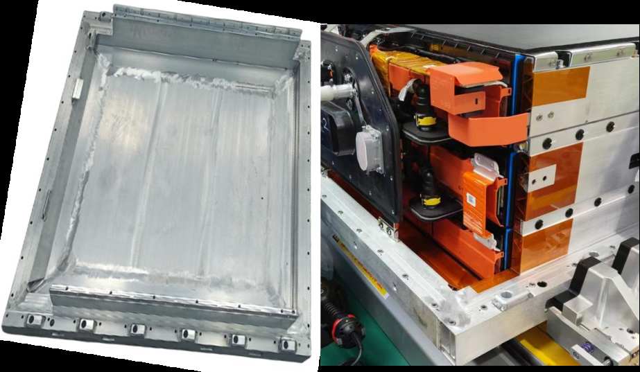
The wave of electric heavy-duty trucks is sweeping across the global logistics and transportation industry, injecting strong momentum into the "dual-carbon" goals. However, with the soaring demand for extended range, battery systems with single-pack capacities exceeding 500kWh or even approaching 1000kWh have become commonplace. This is akin to equipping vehicles with a mobile "energy fortress," but the potential thermal safety risks have also reached unprecedented levels. When the three extreme safety indicators—"ultra-large capacity," "ultra-fast thermal propagation" (<2 minutes), and "ultra-high collision resistance" (>1500kJ)—converge, the industry faces a severe technological gap. This article analyzes these challenges and explores systematic solutions to build a dedicated safety defense line for electric heavy-duty trucks.
Figure 1: Short-Blade Three-Layer Stacking Solution
1-The 500kWh+ Era: Opportunities and Safety Challenges Coexist
a. Capacity Leap Has Become the Norm
To meet the demands of heavy-load, long-distance transportation, the battery capacity of electric heavy-duty trucks has rapidly increased from 200-300kWh to 600kWh+. Industry leaders have rolled out solutions ranging from 500kWh and 600kWh to even 1000kWh, marking the official arrival of the ultra-large-capacity era.
b. The Maturity of LFP (Lithium Iron Phosphate) Battery Technology
LFP batteries have become a major driver due to their advantages in safety and cycle life, making them the mainstream choice for heavy-duty trucks.
2-The "Three Major Challenges" Under Extreme Safety Demands
a. Thermal Propagation Limit Control (<2 Minutes)
· Core Objective: Safety designs must delay or block thermal propagation to create a time window for evacuation and rescue (e.g., the 5-minute early warning requirement under China's GB 38031-2020 standard).
· Harsh Reality: In high-density battery packs exceeding 500kWh, the massive energy released by a single cell during thermal runaway can easily trigger a catastrophic chain reaction. Test data shows extremely rapid thermal propagation: in some cases, it takes only 22 seconds to engulf the entire pack, 5 seconds to ignite adjacent modules, and as little as 44 seconds for inter-module propagation.
· Core Difficulty & Gap: How to effectively ensure inter-module thermal propagation is controlled beyond 2 minutes? Currently, no commercial heavy-duty truck system has publicly claimed or verified compliance with this stringent requirement.
b. Structural Collision Resistance Barrier (>1500kJ)
· Core Requirement: The collision energy of a fully loaded heavy-duty truck far exceeds that of passenger vehicles, easily surpassing 1500kJ. As a structural component of the chassis, the battery pack must possess ultra-high strength to remain intact post-collision, preventing internal cell damage that could lead to thermal runaway.
· Harsh Reality: Current domestic and international standards (e.g., GB/T 31467.3-2015, UNECE R100) lack clear or sufficient thresholds for collision energy testing of heavy-duty truck battery packs. Publicly available certification data for systems passing 1500kJ-level collision tests is extremely scarce. Although higher-energy simulations exist (e.g.,2500kJ), full-system validation remains a significant challenge.
· Core Difficulty & Gap: The absence of clear high-energy collision protection standards and thoroughly validated solutions.
c. Secondary Disaster Chain Risks (Cargo Explosion & Road Paralysis)
· Cargo Explosion Risk: High-temperature flames from battery thermal runaway can easily ignite cargo (especially hazardous materials), forming a disaster chain: "battery runaway → cargo fire → explosion."
· Road Paralysis Risk: Lithium battery fires are difficult to extinguish (requiring large volumes of continuous cooling water) and prone to reignition. A multi-ton heavy-duty truck catching fire on a highway or in a tunnel complicates rescue efforts (high-voltage power cutoff, toxic gas prevention) and takes an extended time (up to several hours, with potential impacts lasting 24 hours), severely disrupting traffic and causing significant societal repercussions.
· Core Difficulty & Gap: The lack of targeted quantitative road clearance time standards and efficient emergency response systems.
3-Building the Defense Line: Thermal Event Early Warning System Design – Four-Layer Protection Net
4-Thermal Management Supporting Solutions: Empowering the Early Warning System
· Liquid Cooling System: Integrated high-efficiency liquid cooling plates eliminate localized hotspots, maintaining a temperature difference of <3°C between cells.
· Modular Design: Independently detachable module structures enable quick replacement of faulty units.
· Intelligent Monitoring Platform: Cloud-based real-time battery health analysis with automatic early warning alerts sent to maintenance teams.
We will regularly update you on technologies and information related to thermal design and lightweighting, sharing them for your reference. Thank you for your attention to Walmate.
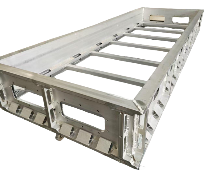
In the new energy heavy truck market, "battery stacking" has become a key term: mainstream models now exceed 370kWh in battery capacity, with 600kWh+ models frequently debuting. This is not just a leap in technical specifications but also the industry's declaration of a full-scale assault on the line-haul logistics market—by enhancing single-charge range, addressing the core user pain point of "range anxiety," and optimizing total cost of ownership (TCO). This article will dissect the business logic and technological breakthroughs behind this trend.
1-Business Logic: Why Must We "Stack Batteries"?
a. Scenario-Driven Necessity
·Closed Scenarios (Short-Distance, High-Frequency): Ports, mines, and similar settings rely on battery-swapping models (3-5 minute recharge), where 280kWh batteries suffice.
·Line-Haul Logistics (Long-Distance Transport): Accounts for 70% of freight volume, requiring a single-charge range of 500+ km. 600kWh+ batteries serve as the "gateway" to this market.
b. The Economics of TCO
Key Conclusion: When daily mileage exceeds 300 km, the TCO of battery-swap heavy trucks begins to outperform diesel trucks.
b. Model Innovation: Resolving Cost Challenges
·Battery-as-a-Service (BaaS): Users purchase the "bare vehicle" with battery leased monthly (¥5,000–9,000), reducing upfront costs by 30%.
·Battery Swap Services: Service fee of ¥0.2–0.5 per kWh, with total energy costs around ¥2.73/km (close to diesel trucks at ¥2.8/km).
·Commercial Validation: A swap station serving 50 vehicles/day can shorten the payback period to 5 years (IRR of 13.1%).
2-Technological Breakthroughs: How to Balance Range and Weight?
a. Spatial Compromise: Chassis for Space
·To prevent batteries from encroaching cargo space, the industry is optimizing battery layout. For example, integrating batteries into the chassis (replacing traditional rear-mounted designs) frees up cargo volume, lowers the center of gravity, and may improve energy efficiency.
·Trade-off: Reduced ground clearance and compromised chassis modularity.
b. Material Science Compromise: Energy Density for Weight
·The key to weight reduction lies in improving battery energy density (more energy stored per unit weight). Higher density enables lighter batteries or extended range at the same weight.
·Core Innovation: Battery materials (e.g., high-nickel cathodes, silicon-carbon anodes).
·Trade-off: Higher energy density often comes with safety risks, shorter lifespan, increased costs, and reduced fast-charging capability—requiring difficult multi-parameter balancing.
c. Business Model Compromise: Network Over Single-Vehicle Pressure
·The battery-swap model shifts the "infinite range" burden from individual vehicles to the swap network. By deploying dense swap stations along routes, trucks only need enough charge to reach the next station, eliminating oversized batteries.
·Outcome: Reduces extreme battery capacity demands, making onboard battery loads more "rational."
d. Residual Value Management: The Core Barrier for BaaS
Battery banks must develop full lifecycle capabilities: State-of-Health (SOH) monitoring, cascading reuse, and recycling systems.
Figure 1: Heavy-duty truck battery pack enclosure
3-Future Trends: From "Battery Stacking" to "Efficient Energy Loading"
a. Technology Evolution: Solid-state batteries will break energy density barriers, rebalancing weight and range.
b. Charging Infrastructure: Standardized heavy-truck swapping protocols and grid synergy (e.g., peak shaving) are critical for scale.
c. Multi-Path Competition: Hydrogen-powered heavy trucks retain substitution potential in long-haul, heavy-load segments.
Conclusion: Phased Strategy, Long-term Evolution
"Battery stacking" is an inevitable choice for electric heavy trucks to conquer line-haul logistics, reflecting a dynamic balance between commercial needs and technical realities. As battery technology advances and business models mature, the industry will shift from a "capacity race" to an "efficiency race." Currently, it is driving China's new energy heavy trucks to complete the critical leap from "niche" to "mainstream."
We will regularly update you on technologies and information related to thermal design and lightweighting, sharing them for your reference. Thank you for your attention to Walmate.
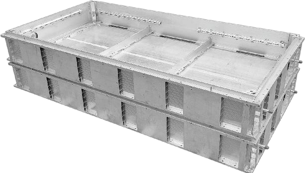
Core of Thermal Management for Heavy-Duty Truck Battery Packs: Dual Breakthroughs in Lightweight Materials and Manufacturing Processes
Heavy-duty trucks (HDTs), as the core force in road logistics, have made the safety, reliability, and cost-effectiveness of their battery systems a key technological focus. The battery tray, as the critical structural component that carries, protects, and manages battery modules, is now facing unprecedented extreme challenges.
Figure 1: Battery tray for electric heavy-duty trucks
1-Extreme Challenges for Heavy Duty EV Battery Tray
a. Stringent Mechanical Durability Requirements: Vibration, Impact, and Million-Kilometer Service Life
Heavy-duty trucks are designed with a service life of ≥1.5 million kilometers, 10 times longer than that of passenger vehicles. The battery tray must continuously withstand the following three types of extreme mechanical loads throughout its entire lifecycle:
·High-frequency random vibrations: When fully loaded and driving on unpaved, construction, or uneven roads, the chassis generates random vibrations across a wide frequency band (5 Hz–2 kHz). These vibrations not only test the fatigue limit of the tray's main frame but also induce microcracks in stress concentration zones such as welds, bolt holes, and flanges, becoming potential failure initiation points.
·High-g transient impact: Deep potholes, emergency braking, or handling drops can generate impact accelerations exceeding 50 g within milliseconds. The tray must instantaneously absorb/dissipate energy to prevent cell displacement, short circuits, or casing rupture.
·Cumulative fatigue damage: A million-kilometer service life means hundreds of millions of vibration cycles. Under alternating stress, aluminum alloys are prone to fatigue crack initiation and propagation, eventually leading to structural fracture. The core design task is to delay crack initiation until after the vehicle's retirement through topology optimization, local reinforcement, hybrid material integration, and process control.
b. Complex Thermal Management and Thermal Cycling Challenges
Due to their ultra-high capacity (hundreds of kWh) and high-power charging/discharging, heavy-duty truck battery packs generate massive heat. They also operate across arctic to tropical environments, facing extreme temperature differentials.
·Wide-temperature-range control: The tray and thermal management system (TMS) must precisely maintain cell temperatures within the optimal 25–40°C range under ambient temperatures ranging from -40°C to +85°C, with <5°C temperature variation between individual cells.
·High-stress thermal cycling: In accelerated aging tests, the system must endure thousands of -40°C ↔ +85°C thermal shock cycles (ramp rate: 5–15°C/min, dwell time: 5–15 minutes). This process causes repeated thermal expansion/contraction at material interfaces (aluminum alloy/sealant/plastic components), posing severe challenges to the reliability of welded/adhesive joints in integrated cooling channels.
2-Mainstream Material Solutions and Multi-Functional Integration Technologies
To address these challenges, the industry has developed a technology roadmap based on high-strength aluminum alloys, evolving toward highly integrated multi-functional designs.
a. Core Material Selection: The Dominance of 6xxx-Series Aluminum Alloys
In competition with steel, magnesium alloys, and composites, 6xxx-series (Al-Mg-Si) aluminum alloys have become the mainstream material for heavy-duty truck battery trays due to their excellent comprehensive performance, mature processing techniques, and high cost-effectiveness.
Key Alloy Grades and Properties:
·6061-T6: The most widely used grade, renowned for its outstanding strength, good weldability, and corrosion resistance.
·6005A-T6 and 6063-T6: Supplementary options, also offering good extrudability, suitable for components with slightly lower strength requirements.
b. Paradigm Shift in Design Philosophy: Thermal Management and Structural Health Monitoring
The design philosophy of modern heavy-duty truck battery trays has undergone a fundamental transformation—evolving from a purely mechanical "load-bearing structure" to a highly integrated "intelligent thermal regulation platform." This shift is primarily manifested in two key technological directions:
·Integrated Thermal Management (Mature Application)
Currently the most technologically mature and widely adopted approach, its core concept involves embedding cooling functionality directly into the tray's structural design to achieve compact and efficient thermal regulation.
·Structural Health Monitoring (SHM) Exploration (Early Stage)
This emerging technology aims to preemptively detect potential structural damage (e.g., cracks, deformations) during long-term service. However, it remains in the validation and laboratory research phase, lacking large-scale commercial deployment cases or sufficient long-term operational reliability data.
3-Analysis of Core Manufacturing Process Routes
The manufacturing processes for heavy-duty truck battery trays directly determine their cost, performance, and production efficiency. The mainstream approach combines aluminum extrusion and friction stir welding (FSW), optimally balancing performance requirements with small-to-medium batch production models.
a. Aluminum Extrusion
This process shapes aluminum billets into elongated structural components (e.g., crossbeams, longitudinal beams) via dies. As the cornerstone technology for battery trays, it offers:
·Advantages: Low mold costs, short development cycles, and adaptability to large, non-standardized parts in small batches.
·Limitations: Requires cutting, machining, and multi-step welding assembly, resulting in low automation, slower cycle times, and inferior efficiency compared to integrated die casting.
b. Friction Stir Welding (FSW)
A solid-state joining technology, FSW generates heat via a rotating tool to achieve high-strength aluminum welds, making it the premier choice for load-bearing/sealed joints:
·Performance: Weld strength reaches 80–90% of the base material, with no porosity/cracking defects. Minimal thermal distortion ensures IP67+ sealing and eco-friendliness.
·Constraint: Limited to flat/simple-curved weld geometries.
Aluminum alloy heavy-duty truck battery trays have transcended their role as high-strength lightweight structures to become multifunctional integrated platforms. However, proliferating functionalities introduce challenges like multi-physics coupling failures, process complexity, and reliability risks. Future breakthroughs will hinge on material-process-system co-innovation, leveraging adaptive interfaces and digital twin technologies to enable the safe and sustainable evolution of intelligent trays.
We will regularly update you on technologies and information related to thermal design and lightweighting, sharing them for your reference. Thank you for your attention to Walmate.

5 Optimization Guidelines for Energy Storage Liquid Cooling Plate Design Amid the 500Ah+ Large Battery Cell Wave
Cost-Driven Large Cell Revolution and Cooling Challenges:The energy storage industry is undergoing a profound transformation driven by "cost reduction and efficiency enhancement" – the rapid rise of the large cell technology roadmap. 300Ah+ cells are becoming standard, while 500Ah and even higher capacity cells are accelerating their deployment. While this revolution enhances system energy density and reduces per-watt-hour costs, it also presents severe challenges: a dramatic increase in individual cell mass, a surge in module/pack (battery pack) overall weight, multiplying the load-bearing pressure on bottom support structures; larger heat generation power and longer internal heat transfer paths impose extreme demands on the efficiency and uniformity of the thermal management system. As the core of pack thermal management, liquid cold plates face the brunt of the upgrade pressure.
Traditional "thin-plate covering" cold plate designs are no longer sustainable. Under constraints of limited space and stringent cost control, cold plates must transcend their single function of heat dissipation and evolve towards a trinity of "structural-functional integration, ultimate heat dissipation efficiency, and system lightweighting." This article will delve into this advanced design pathway.
1-Structural-Functional Integration: The "Load-Bearing Revolution" of Cold Plates
As cell mass significantly increases, the loads borne by the enclosure baseplate and the cold plate surge dramatically. Designing the cold plate as a load-bearing structural component is the key breakthrough point for resolving the conflicts between weight, cost, and space.
a.Becoming the Enclosure's "Skeleton": Integrated Load-Bearing Baseplate
Design Concept:The cold plate no longer attaches to the enclosure baseplate; instead, it becomes the primary load-bearing structure of the enclosure itself.
Core Advantages: Significantly reduces traditional baseplates and mounting brackets, markedly lowering system weight and material costs, and simplifying the assembly process.
Technical Requirements: Must demonstrate extremely high bending, compression, and impact resistance stiffness and strength.
b. Embedding "Steel Reinforcement": Topology Optimization and Reinforcement Structures
Mechanics-Led Design: Utilize CAE simulation for topology optimization, integrating stiffening ribs, etc., within non-critical heat dissipation areas of the cold plate (e.g.flow channel gaps, edges).
Efficient Material Utilization: Optimized design ensures material is distributed along critical stress paths, removing redundant material, achieving lightweighting while guaranteeing load-bearing capacity.
c.Module-Level Load-Bearing Platform: Consolidating Components
Large-scale, high-strength cold plates can directly serve as the mounting baseplate and load-bearing skeleton for modules. Cells or modules are fixed directly onto them, eliminating the need for additional support frames, further streamlining the structure and improving volumetric efficiency.
2-Significant improvement in heat dissipation performance: the art of balancing efficiency and equation
The core pain points of large battery cells are the difficulty in dissipating heat in the central area and controlling the overall temperature difference. The design of liquid cooled plates requires innovation from multiple dimensions including flow channels, interfaces, and materials.
a. Flow channel design: from "simple pipeline" to "intelligent blood vessel"
·Precise diversion and enhanced turbulence: Adopting a tree branch flow channel, serpentine+turbulence column/fin composite structure, to increase flow and disturbance in the high heat zone of the cell center. Avoid the "fast edge cooling and slow center cooling" caused by the straight path with large drift diameter.
·Variable cross-section and zone cooling: Based on the heat generation in different areas of the battery cell (such as center>edge), design gradient cross-section flow channels or independently controllable zone circuits to achieve precise and on-demand heat distribution, with temperature difference control up to ± 2 ℃.
·Biomimetic and Topology Optimization of Flow Channels: Utilizing CFD and topology optimization techniques to generate an efficient and low resistance "natural growth" flow channel network, maximizing heat transfer area and efficiency, and reducing pump power loss.
b. Breaking through interface thermal resistance: making "contact" tighter
·High performance interface material (TIM): research and develop high thermal conductivity (>5W/mK), low thermal resistance, long-term stable thermal conductivity gasket/gel/phase change material, and take into account insulation, cushioning and processability.
·Microstructure surface engineering: Processing micro grooves, array micro protrusions, or applying special coatings on the contact surface of the cold plate to increase the effective contact area, enhancing contact through capillary force, and significantly reducing interface thermal resistance (can be reduced by 30% -50%).
c. Material Upgrade: Dual Pursuit of Thermal Conductivity and Strength
Exploring higher thermal conductivity aluminum alloys (such as high thermal conductivity 6-series and specific 7-series alloys) or aluminum based composite materials (AMCs) while ensuring structural strength, to enhance basic thermal conductivity.
3-Lightweight throughout: a weight game where every gram is worth fighting for
Every gram of weight loss means reduced costs and improved transportation and installation efficiency.
Refined 'slimming' design:
a. Simulation driven thinning: Through precise CAE calculations, the maximum thinning of the cold plate wall thickness is achieved while meeting strength, stiffness, and heat dissipation requirements (such as reducing from 2.0mm to 1.5mm).
b. Hollow structure and hollow out: Design hollow cavities or perform safe hollow out treatment inside the reinforcing ribs and non critical areas.
c. Application of high-strength materials: Using higher strength aluminum alloys (such as 7xxx series) to achieve thickness reduction and weight reduction under the same performance.
4-Manufacturing process: the cornerstone supporting advanced design
The "structuring" and "complexity" of liquid cooled plates pose higher requirements for manufacturing processes.
Upgrading and integration of mainstream processes:
·Aluminum extrusion+Friction Stir Welding (FSW): advantages lie in large size and high structural strength. Advanced direction: Developing complex profile sections with integrated flow channels and reinforcing ribs; Breakthrough in ultra long and variable cross-section FSW welding technology to ensure weld strength and airtightness.
·Stamping+brazing: The advantage lies in flexible channel design and great potential for lightweight. Advanced direction: Achieving precision stamping of deeper and more complex flow channels; Improve the yield and joint reliability of large-sized and multi-parts-brazing; Integrate reinforced structures on stamped parts.
·High pressure die-casting: The potential lies in manufacturing highly integrated and extremely complex-shaped cold plates (with integrated flow channels, rib positions, and interface oneness) .Challenges such as mold cost, internal channel surface smoothness, and pore control should be overcome.
·Hybrid process innovation: Multi process combination innovation, integrating the advantages of different processes to meet more complex design requirements.
5-Reliability: the lifeline of integrated design
When the liquid cooled plate becomes the core of the structure, its reliability is related to the safety of the entire PACK.
Strengthen the dual reliability of "structure-fluid":
a. Extreme mechanical verification: It is necessary to simulate extreme working conditions through vibration, impact, compression, and drop tests that far exceed the standard.
b. Fatigue life guarantee: Conduct detailed structural fatigue and pressure cycle simulation and testing to ensure no leakage or cracking under long-term alternating loads.
c. Redundant sealing design: Key interfaces and the use of multiple sealing strategies.
d. Strict quality control: Introducing automated online testing to ensure manufacturing consistency.
The advanced path of energy storage liquid cooled plates is a vivid epitome of technological innovation driving industry cost reduction and efficiency improvement. Whoever can win the first place in the design competition of "structural functional integration" will have an advantage in the competition of the trillion dollar energy storage market. This silent 'bottom plate revolution' is quietly reshaping the future form of energy storage systems.
We will regularly update you on technologies and information related to thermal design and lightweighting, sharing them for your reference. Thank you for your attention to Walmate.

The essence of IGBT heat dissipation is the problem of heat transfer efficiency under multi-layer thermal resistors in series, among which the interface thermal resistance accounts for more than 60% and is the main optimization object.
Figure 1: IGBT thermal resistance diagram
1-The root of the problem: Where is the thermal resistance hidden?
The thermal resistance of the IGBT module is a complex multi-layer structure involving multiple material layers and heat conduction paths. The thermal resistance of the IGBT module is mainly composed of the thermal resistance (Rth) of the IGBT module, which is composed of the junction-case thermal resistance (Rth-Rjc) and the case-ambient thermal resistance (Rth-Rca) in series:
a. Junction-case thermal resistance (Rth-Rjc):
· Copper-clad ceramic board is the main bottleneck: accounting for more than 75% of Rth-Rjc, because its ceramic layer (such as Al₂O₃) has low thermal conductivity (15–35 W/m·K) and its thickness cannot be ignored.
· Other levels account for the remaining 25% of the chip thermal resistance (silicon-based thermal conductivity ≈ 150 W/m·K), solder layer thermal resistance (voids cause interface thermal resistance), and copper substrate thermal resistance (high thermal conductivity but small thickness effect). b. Shell-ambient thermal resistance (Rth-Rca):
· Interface contact thermal resistance is dominant: The thermal resistance of the thermal grease/contact surface between the substrate and the heat sink accounts for 40–60% of the total thermal resistance, and accounts for more than 60% in the traditional single-sided heat dissipation design.
· Influence of heat dissipation structure: For example, in an air-cooled heat sink, the contact thermal resistance (Rjc), thermal conductivity thermal resistance (Rch), and heat exchange thermal resistance (Rha) account for 65.9%, 5.9%, and 28.2% respectively (conventional fin structure).
2- Path to overcome thermal resistance: Coordinated optimization of materials and structures
a. Chip thinning: reducing internal thermal resistance
· Technological evolution: Thinning from 200μm PT wafer to 70μm for IGBT7, reducing thermal resistance by 60%. Thinning process (grinding/CMP/plasma etching) can release stress and improve thermal diffusion efficiency.
· Physical mechanism: The thickness is reduced from 350μm to 110μm, and the heat capacity per unit area (Cth) is reduced from 786.5 J/℃·m² to 247.2 J/℃·m², accelerating transient heat dissipation. After thinning, the resistance is reduced, the ohmic contact is enhanced, and the failure risk caused by internal stress is reduced.
b. Interface innovation: silver sintering replaces thermal conductive silicone grease
Interface material upgrade is the core of reducing contact thermal resistance:
Table 1: Comparison of thermal conductivity between silver sintering and thermal conductive silicone grease
c. Substrate upgrade: high thermal conductivity ceramics and diamond
Substrate materials are undergoing a key evolution from Al₂O₃ to AlN and then to diamond. The core goal is to significantly improve thermal conductivity to meet the heat dissipation needs of higher power density electronic devices.
· Breakthrough of AlN substrate
The thermal conductivity can reach 5–10 times that of Al₂O₃. The thermal expansion coefficient (about 4.5 ppm/K) is closer to silicon (about 2.6 ppm/K), which effectively reduces the thermal mismatch stress between silicon chips.
· Prospects of diamond substrates: Thermal conductivity exceeds 2000 W/(m·K) (80 times that of Al₂O₃), thermal expansion coefficient is 1.1 ppm/K, perfectly matching silicon chips. The thermal conductivity of diamond/aluminum composite materials reaches 613 W/(m·K) (2.6 times that of pure aluminum), and interface optimization improves bonding strength.
Table 2: Comparison of key substrate material properties
3- Challenges of overcoming thermal resistance
a. Mechanical strength bottleneck of chip thinning
Reducing the thickness from 200μm to 70μm (IGBT7) can reduce thermal resistance by 60%, but further thinning to 20μm will cause the risk of fracture. Ultra-thin chips (<50μm) are prone to microcracks due to mismatch of thermal expansion coefficient (CTE).
b. Challenge of high thermal conductivity substrate
Table 3: High thermal conductivity substrate challenges
c. Interface reliability: Multi-physics coupling challenge
· Risk of silver sintering CTE mismatch: The silver sintering layer (CTE=18.4 ppm/K) differs by 4 times from the SiC chip (CTE=4.5 ppm/K), and thermal cycling is prone to delamination.
· Interface contact pressure control: Pressure 0.1→0.5 MPa can reduce thermal resistance by 40%, but >1 MPa will squeeze out the silver layer.
When IGBT power density enters the 10kW/cm² era, heat dissipation design has leaped from "auxiliary engineering" to "system bottleneck breakthrough point". The substrate revolution from Al₂O₃ to diamond, the interface transition from silicone grease to copper sintering, and the chip slimming from 200μm to 50μm are essentially a battle against the second law of thermodynamics. Heat dissipation design is approaching the physical limit, and the triangular synergy of materials, structure and process will become the key to breaking through.
We will regularly update you on technologies and information related to thermal design and lightweighting, sharing them for your reference. Thank you for your attention to Walmate.
Aluminum replacing copper has become an irreversible trend in the field of Skived fin heat sinks. The core driving forces are cost, lightweight and resource security, and the performance gap is made up through process innovation (skiving technology, microchannel design). In typical applications, aluminum solutions have been widely used in high-efficiency scenarios such as data centers and new energy vehicles. However, aluminum replacing copper is not a simple material replacement, but a systematic project that requires comprehensive optimization from material selection, structural design, manufacturing process to application scenarios to achieve the best balance between cost and performance. This article will explore in depth the key technological breakthroughs and application solutions in this replacement practice.
1-Aluminum vs. Copper: Material Properties and Replacement Challenges
To scientifically evaluate the feasibility of aluminum replacing copper, we must first understand the differences in the core physical properties of the two metals in heat dissipation applications:
Table 1: Comprehensive comparison of aluminum and copper heat dissipation material properties
The performance of the heat sink depends not only on the thermal conductivity of the material, but also on the heat capacity characteristics and surface area utilization. The difference in physical properties between aluminum and copper determines the feasibility boundary of substitution:
a. The dialectical relationship between thermal conductivity and heat capacity
·Instantaneous advantage of copper: high thermal conductivity (385W/m·K), faster initial heat diffusion;
·Steady-state breakthrough of aluminum: high specific heat capacity (900J/kg·K, 2.3 times that of copper), 133% increase in heat storage capacity per unit mass, low density (2.7g/cm³, 30% of copper), 40% increase in heat dissipation area for the same volume, and long-term balance achieved through a larger surface area during the continuous heat dissipation stage.
b. Thermal matching addition
The thermal expansion coefficient of aluminum (23.1×10⁻⁶/K) is close to that of PCB substrate (13-18×10⁻⁶/K), reducing the risk of thermal stress failure.
In addition, the trend is being driven by a change in performance perspective - accepting a reduction in local thermal conductivity in exchange for system-level lightweighting, cost optimization, and improved sustainability.
2-Key breakthroughs in manufacturing process
a. Material system breakthrough: alloy composition optimization and hardness control
· Traditional pain points: Traditional aluminum materials (such as 1060 pure aluminum) have low hardness (24-38HB) and are easy to skived fin, but subsequent machining is prone to sticking to the tool; 6063 aluminum alloy has high hardness (34-42HB), which is conducive to later processing, but the skived height is limited (≤50mm).
· Breakthrough point: Through alloy composition optimization (Si 0.25%, Mg 0.41%) and melting and casting process innovation (556℃ homogenization + 430℃ extrusion/490℃ quenching), the hardness of aluminum materials is controlled in stages: maintain a low hardness of 32-39HB before skived fin (to ensure 70mm high fin processing), and strengthen to 55-64HB after skived fin (to solve the problem of sticking to the tool during machining).
·Impurity control and thermal conductivity balance: With high purity control of Fe≤0.11% and Cu≤0.02% (99.70% aluminum base), high thermal conductivity is maintained while improving machining efficiency, so that high fin aluminum radiators have both processing performance and service strength.
b. The essential difference between material hardness and cutting response: The core advantage of aluminum in achieving ultra-thin fins lies in its work hardening characteristics and cutting force requirements.
Technical analysis:
·The soft properties of copper lead to the process of skived fin: tool extrusion easily causes material accumulation at the root of the fin (forming a "curling effect")
The thin film area has severe plastic deformation (high instability rate when the thickness is <0.1mm); the degree of work hardening is weak, and the structure cannot be strengthened by deformation.
·When skiving aluminum alloy: work hardening significantly improves the stiffness of the fin (the strength of 6063 alloy is improved after cold hardening); low cutting force allows the use of more precise thin-blade tools; small elastic recovery (about 1/3 of copper) to ensure the geometric accuracy of the fin.
c. Breakthrough in structural limits and cost optimization
The design of ultra-thin fins is essentially to maximize the surface area/volume ratio, and the physical properties of aluminum are more suitable for this goal:
Table 2: Comparison of parameters of aluminum and copper skived fin heat sinks
Simple cross-section aluminum profiles (plate/groove) are used to replace complex molds, reducing mold costs by 60%. Small-batch production directly uses plate skived fin (mold-free) to adapt to customized needs.
3-Trend Essence: System Optimization Replaces Material Egoism
The core value of aluminum skived fin heat sink lies in the comprehensive optimization of the system level, rather than the replacement of a single thermal conductivity performance:
·Technical leverage: Achieve a synergistic breakthrough in lightweight and efficient heat dissipation through high-multiple fins structure, thin fin process and one-piece molding;
·Lightweight integration advantage: In emerging fields such as new energy/5G, lightweight and cost have become more critical indicators than absolute thermal conductivity, and derivative benefits have been improved.
·Full-cycle economy: The initial cost is only 45% of the copper solution, and the fan power consumption reduction brought by lightweighting can achieve rapid investment recovery.
·Sustainable manufacturing foundation: The industry characteristics of sufficient aluminum production capacity and recovery rate>95% provide guarantee for supply chain stability.
Do you want to balance skived fin heat sink performance and cost? Click to learn key solutions for heat sink material selection and equipment optimization:Core advantages of skiving process: heatsink material selection and equipment precision optimization guide
We will regularly update you on technologies and information related to thermal design and lightweighting, sharing them for your reference. Thank you for your attention to Walmate.

The leap in power density and the game of thermal boundaries are driving the four revolutions in solar inverter cooling technology. From the centralized H-bridge's fin air cooling to the three-level NPC topology's use of heat pipes to tame the heat source; from modular multi-levels to build a thermal redundancy defense line with phase change materials, to SiC soft switches using microchannel liquid cooling to break through the high wall of heat flux density - every topology iteration is rewriting the cooling paradigm. The essence of this evolution is the ultimate challenge of power electronics to the second law of thermodynamics under the triangular constraints of efficiency, power density, and reliability, and it will define the competitive barriers of the next generation of photovoltaic storage fusion systems.
1-Evolution of solar inverter system
The evolution of solar inverter system follows the four-step transition of heat dissipation adaptation → thermal management → thermal synergy → entropy reduction system, driving form from cabinet-type centralization to chip-level intelligent integration, power density continues to break through, efficiency and scene penetration simultaneously leap.
a. The physical form of solar inverter has undergone three-level transition:
Early centralized inverters were large in size (>1m³/MW) and weighed more than a ton; the subsequent string-type solution disassembled the power unit into 20-100kW modules, and the volume was reduced to 0.3m³/MW; the current modular design has been further advanced to 10kW sub-units, the power density has exceeded 50kW/L, and the weight has dropped to <15kg/kW.
b. Environmental adaptability shifts from passive protection to active adaptation:
· Protection level: IP54 → IP66/C5-M anti-corrosion (coastal/salt spray scenarios)
· Temperature range: -25~+60℃ → -40~+85℃ (extreme cold/desert scenarios)
· Intelligent response: Dynamic temperature control algorithm adjusts heat dissipation power in real time to match dust/high humidity environments
c. Heat dissipation demand changes qualitatively with the leap in power density:
Early forced air cooling copes with heat flux density of <100W/cm²; heat pipe technology in the three-level era solves the problem of multi-heat source temperature uniformity; SiC high frequency promotes the popularization of liquid cooling; microchannel phase change cooling is becoming a standard solution for >300W/cm², and the proportion of the heat dissipation system has been reduced from 30% to 12% of the whole machine.
2- Evolution of solar inverter system topology and thermal management
The underlying logic of the evolution of solar inverter system topology is driven by "efficiency-power density-cost":
· Changes in loss mechanism: from conduction loss dominated (H-bridge) → switching loss core (NPC) → high-frequency magnetic parts/capacitor loss (MMC) → electromagnetic compatibility loss under SiC soft switching accounts for more than 60%, pushing the heat dissipation focus from "average temperature" to "ultra-high heat flux density management";
· Power density transition: The physical limit of silicon-based IGBT (20kHz/3kW/L) was broken by SiC devices (100kHz/50kW/L), forcing the heat dissipation solution to jump from air cooling → heat pipe → liquid cooling → microchannel phase change cooling;
· Dynamic balance of cost: The proportion of heat dissipation system cost gradually decreases from H-bridge to SiC, but the unit power heat dissipation cost increases instead. It is necessary to reconstruct the thermal boundary through topology-packaging-heat dissipation collaborative design to ultimately achieve a reduction in LCOE.
Table 1: Evolution of solar inverter topologies and thermal management
Faced with the engineering challenges of the continuous leap in power density and continuous breakthrough in heat flux density of photovoltaic inverters, the heat dissipation solution needs to be systematically upgraded:
· Evolution from air cooling to liquid cooling: to cope with the high heat flux density characteristics of new chips, significantly reduce the core temperature;
· Combination of heat pipe and phase change technology: effectively suppress the thermal shock of modular systems and extend the life of key components;
· Collaborative design and cost control: optimize the proportion of heat dissipation system through deep integration of electrical and thermal management.
As a thermal management partner, Walmate focus on direct-to-chip cooling technology and system-level thermal resistance optimization to provide feasible heat dissipation solutions for photovoltaic storage systems.
We will regularly update you on technologies and information related to thermal design and lightweighting, sharing them for your reference. Thank you for your attention to Walmate.

This article attempts to sort out the innovation path of HVDC system heat dissipation technology under the background of AI computing power explosion, focusing on two major directions: liquid cooling synergy and material upgrade. The content is compiled from industry public information. If there are any omissions, please correct them.
1- The rise of HVDC and the inevitability of upgraded cooling demand
The explosive growth of AI computing power has significantly increased the power density of data centers (single cabinet exceeds 100kW), driving the demand for high-efficiency power supply systems. Traditional UPS faces efficiency and floor space challenges, while HVDC systems are rapidly becoming the mainstream power supply solution for AI data centers with their high efficiency, low loss, small size and high reliability. This directly drives the rapid growth of the HVDC market and the surge in penetration in AI data centers. At the same time, AI demand also prompts HVDC technology to develop to higher voltage levels (such as 750V and 1000V systems) to further improve efficiency and power carrying capacity.
a. AI computing power explosion and energy efficiency requirements
In order to meet high energy efficiency standards (such as data center PUE≤1.5/≤1.3), HVDC cooling technology needs to achieve:
· Efficient cooling design, using liquid cooling technology to cope with high power density; precise control of cooling parameters.
· Optimization of heat transfer media, preferential use of deionized water, and selection of stable fluids that prevent phase separation (such as PCD) in special scenarios.
·The radiator performance is upgraded, and high thermal conductivity materials are used; the special flow channel design improves the heat exchange efficiency.
·Dynamic temperature control and monitoring, real-time monitoring of key point temperatures; equipped with diagnostic equipment to predict faults.
·Redundancy and reliability design, such as: N+1 redundant configuration of cooling system, dual-circuit chilled water pipe network to prevent single point failure.
·Emergency heat dissipation capacity, support heat dissipation under extreme working conditions.
·Environmental adaptability, ensure stable operation at an ambient temperature of 15-35℃, and take into account moisture-proof ventilation.
b. Deepening application of third-generation semiconductors (SiC/GaN)
The surge in AI computing power has promoted 800V high-voltage DC architecture to become a new trend in data centers:
·SiC/GaN gradually replaces traditional silicon-based devices with its high power density, high-frequency switching, and low loss characteristics.
·Significantly improve system efficiency.
·Reduce material costs and enhance reliability.
c. Energy efficiency advantages of HVDC vs. AC power supply and its heat dissipation impact
The requirements of HVDC architecture for heat dissipation systems are mainly reflected in high power density, efficient cooling methods, redundant design, environmental adaptability, energy efficiency optimization, and fast fault recovery. These requirements jointly determine the complexity and challenges of HVDC systems in design and operation.
Table 1: Breakdown of the root causes of differences in HVDC vs AC energy conversion losses
2- Innovation core: Liquid cooling synergy and material upgrade solutions
a. Liquid cooling system: Generational transition from edge to mainstream
Liquid cooling penetration rate has risen rapidly, AI computing power drives GPU power consumption to 1000W, forcing air cooling to transform, and edge scenarios need to adapt to the extreme temperature range of -30℃~60℃.
Table 2: Generational transition of technology paths
b. Material upgrade: a key breakthrough in coping with extreme thermal challenges
Material upgrade promotes breakthroughs in heat dissipation performance: Optimize thyristor thermal management through high thermal conductivity interface materials, combine aluminum nitride ceramic substrates (thermal conductivity ≥ 180W/mK) to enhance the heat dissipation capacity of SiC/GaN devices, and use a composite liquid cooling structure to support high power density. At the system level, N+1 redundant liquid cooling architecture, intelligent temperature control strategy and 800V withstand voltage pipeline design are used to achieve safe and efficient collaborative heat dissipation.
3-Technical Challenges and Opportunities in the Cooling Industry Chain
a. Key Challenges: Standardization and Compatibility Bottlenecks
The lack of uniformity in the interface of the chip-level cold plate and the difference in the withstand voltage of the cabinet-level pipeline (500V~800V) lead to poor compatibility and increase the cost of transformation; the cold plate and immersion technology routes are separated, and the lack of coolant insulation standards exacerbates the fragmentation of the industry; there are hidden dangers in the operation and maintenance link such as insufficient leakage detection mechanism and blank standards for coolant performance attenuation. The root cause lies in the ecological division of the three parties of chip vendors/server vendors/liquid cooling solution providers, forming an "islandization" dilemma with unclear responsibilities.
b. Collaboration Opportunities: Technical Collaboration and Industrial Collaboration
The chip layer promotes the standardization of cold plate interfaces, and the system layer links HVDC load and cooling flow rate through AI temperature control algorithms; the industrial layer relies on ODCC to establish interface and coolant standards, and shortens the deployment cycle with modular whole machines; innovates coolant regeneration technology and equipment leasing models to reduce costs, and covers leakage risks through insurance mechanisms to achieve three-dimensional collaboration of technology-industry-finance.
At present, HVDC cooling technology still faces challenges such as standardization and compatibility, but industrial collaboration has shown signs of breakthrough. This article is only a temporary observation, and we look forward to discussing optimization directions with colleagues in the industry.
We will regularly update you on technologies and information related to thermal design and lightweighting, sharing them for your reference. Thank you for your attention to Walmate.
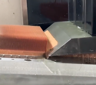
For heat sink manufacturing, material selection and skiving fin accuracy are the key to success. Faced with the stringent requirements of ultra-thin fin and high-density fin, the core challenge is: how to balance material thermal conductivity, cost and processability? How to break through the equipment limit, achieve micron-level stable accuracy, and ensure tooth shape consistency and heat dissipation efficiency? This directly determines product performance, cost competitiveness and mass production yield.
1-Core issues and challenges of the process
a. Process essence: Layered scraping (rough → fine machining) forms high-density fin pieces
Layered scraping quickly removes excess through rough machining and ensures fin shape accuracy through fine machining, but faces three major contradictions:
· Thermal deformation control: The high cutting heat generated by rough machining causes local expansion of thin-walled fin pieces. The deformation needs to be compensated during fine machining, otherwise ellipticity errors (such as uneven spacing of heat dissipating fins) will occur.
· Stress balance: The accumulation of residual stress in layered machining causes warping of tooth pieces, especially aluminum (high thermal conductivity but low yield strength), which needs to reduce cutting force through the "small cutting depth and fast feed" strategy.
· Precision transfer: The jagged residual material left over from rough machining increases the load on the fine machining tool, which is easy to cause chatter and lead to fin thickness tolerance.
b. Two major pain points
· Heatsink material selection: Heatsink material selection needs to balance thermal conductivity, processability and cost. Through performance comparison and selection decision-making, combined with material modification and cost control, synergistic optimization can be achieved.
Table 1: Quantitative comparison of material properties and selection logic
· Equipment accuracy: Equipment accuracy optimization improves machining accuracy and tool life by suppressing cutting thermal deformation, tool wear and error, using innovative tools and thermal-mechanical coupling error compensation.
Table 2: Causal chain of precision defects
2-Material selection: the key to performance and cost
a. Thermal conductivity demand dominates
· High heat flux scenario (>100W/cm²): Copper (thermal conductivity 380W/m·K) is preferred, and its heat carrying capacity is 30% higher than that of aluminum.
Risk control: Pickling to remove the oxide layer (10% HNO₃) + benzotriazole oil film to prevent secondary oxidation, reducing tool wear by 40%.
Medium and low heat flux scenario (<80W/cm²): Pure aluminum is preferred (thermal conductivity 210W/m·K), which meets most consumer electronics needs and costs only 30% of copper.
b. Cost constraint optimization
· Cost-sensitive projects, material thinning (e.g., aluminum substrate from 4mm→2mm); waste recycling (copper chip recovery rate>95%); local composite design (copper is used only in the heat source contact area).
· Alternative solution, pure aluminum + heat pipe design, equivalent thermal conductivity 200–220W/m·K.
c. Compromise of processing difficulty
· For high fin requirements (>70mm), choose pure aluminum, the fin height limit is 120mm, and the bending resistance is stronger than copper; pretreatment, pre-annealing of aluminum (reducing residual stress) to reduce hardness fluctuations.
· For high-precision fin shape (fin thickness <0.5mm), choose 6 series aluminum, AL6063 is hardened after soft processing, and the fin thickness can be controlled to 0.25mm; Taboo, avoid direct processing of hard copper materials (easy to collapse teeth), low-temperature pretreatment is required.
3- Equipment precision optimization: the core of improving yield rate
Equipment precision is the core of the skiving process to achieve high-density fins and control deformation and wear.
Table 3: Impact mechanism of equipment error sources on yield
Ideas for optimizing the precision of skiving equipment:
· Core precision improvement: CNC substitution, replacing mechanical transmission with CNC system to eliminate indexing error; thermal deformation suppression, using cold air cutting technology and combining compensation technology to actively control thermal deformation during processing; tool strengthening, applying CBN coating and optimizing geometric structure to improve tool anti-chipping ability.
· Key achievements: Equipment processing accuracy reaches ±0.003mm (micrometer level); successfully supports the design of extreme fins with a thickness of 0.3mm and a fin height of 120mm; production yield has achieved a significant leap from 65% to 95%.
In summary, precise material matching and extreme skiving accuracy are the core barriers of radiator manufacturing. Optimized materials guarantee the foundation of performance, while micron-level precision equipment (CNC transmission, thermal deformation suppression, and durable tools) is the only way to achieve high yield and support extreme fin shape design. Only by continuously optimizing these two cores and proactively deploying advanced precision control technologies can we consolidate the market leading position of radiator processing.
We will regularly update you on technologies and information related to thermal design and lightweighting, sharing them for your reference. Thank you for your attention to Walmate.
The soaring computing power of AI servers is encountering "thermal constraints" - the power density of chips exceeds 1000W/cm² (such as NVIDIA H100), the power density of cabinets jumps from 2.4kW to 120kW, and the traditional air cooling solution reaches the physical limit of 8-10kW. The underlying logic of this "heat dissipation crisis" is the result of the quantum effect dilemma of chip architecture (the leakage rate surges below 3nm), the energy consumption imbalance of data handling (accounting for more than 90% of system power consumption), and the exponential demand for large model training (GPT-4 consumes 32.4TWh of electricity for a single training). Faced with strong policy constraints (China's PUE ≤ 1.25) and the pressure of energy efficiency, liquid cooling technology has moved from marginal experiments to mainstream and has become the key to unlocking AI computing power.
1-The underlying logic of AI server cooling requirements
a. Chip architecture and power consumption revolution
The computing power density (computing power output per unit area or per unit power consumption) and power consumption of AI chips are the core indicators for measuring their performance. The following is an analysis through three typical chip cases:
As computing power continues to upgrade, chip performance cannot be fully released due to the physical constraints of heat dissipation and energy efficiency. This "power consumption wall" phenomenon stems from:
· Heat dissipation lag, the growth rate of chip power density (>1000W/cm²) far exceeds the iteration speed of heat dissipation technology, and traditional solutions reach physical limits.
· Unbalanced energy consumption structure. At the physical level, the quantum tunneling effect below 3nm weakens energy efficiency improvement, and 3D stacking causes a sharp drop in heat dissipation efficiency by 30%-50%; at the architectural level, data handling energy consumption accounts for more than 90%, and the computing power growth rate (750 times/2 years) and memory bandwidth (1.4 times/2 years) are seriously out of balance; at the application level, large model parameter explosion (such as GPT-4 training consumes 32.4TWh) and dynamic load (instantaneous power consumption exceeds TDP by 200%) increase heat dissipation pressure.
Figure 1: The integration of storage and computing
b. Transition of cabinet power density
Cabinet power density is undergoing a revolution from general computing to AI-driven ultra-density, and the paradigm has been reconstructed from "equipment room adaptation" to "equipment definition room". AI computing power demand has forced the infrastructure to upgrade by leaps and bounds.
· Exponential transition, the global average density increased from 2.4kW/cabinet to 9.5kW/cabinet (CAGR≈12%) from 2011 to 2024, and the AI intelligent computing center has pushed the density to exceed 120kW/cabinet (such as NVIDIA GB200 NVL72), and may reach MW level in 2030.
· Core drive, the surge in AI chip power consumption (H100 single card 700W → GB200 single card 1200W) and the demand for large model training (GPT-4 single training consumes 32.4TWh of power) form a "double helix effect", forcing cabinet density to match the surge in computing power.
· Technological breakthrough, air cooling limit (8-10kW) is replaced by liquid cooling, cold plate type (20-50kW) and immersion type (50-120kW) support high density; power supply system upgraded to high voltage direct current (HVDC), efficiency> 98%; space utilization rate increased by 40% (air duct removed), liquid cooling reduces PUE to 1.08.
c. Policy and energy efficiency driven
· China's "East Data West Computing" project: mandatory requirements for eastern hub nodes PUE ≤ 1.25, western ≤ 1.2, forcing the popularization of liquid cooling technology. Taking the Inner Mongolia hub as an example, the use of immersion liquid cooling can reduce PUE to 1.08, saving more than 20 million kWh of electricity annually.
· Global carbon emission regulations: The EU CSRD directive requires data centers to disclose their full life cycle carbon footprint, and California's "Climate Enterprise Data Accountability Act" includes scope 3 emissions in mandatory disclosure. Liquid cooling technology has become the key to compliance due to the reduction of indirect emissions (such as refrigerant leakage).
· Economic benefit leverage: Liquid cooling saves 30%-50% of cooling energy compared to air cooling. Combined with the difference in peak and valley electricity prices, the investment payback period can be shortened to 3-5 years.
2- Evolution of heat dissipation technology and differentiation of technical routes
a. Liquid cooling technology: from edge to mainstream
The transition of liquid cooling from "edge experiment" to "heat dissipation base" is a rebalance between computing power density and energy efficiency, and a reconstruction of the data center value chain.
· Evolution process, marginalization stage (1960s-2010s), only used for supercomputing/military industry (such as Cray-2), limited by material corrosiveness and high cost; breakthrough period (2010s-2020s), GPU thermal density exceeded 500W/cm² (NVIDIA P100) and policy (China PUE≤1.25) drove commercial use, and the cost of cold plate transformation was reduced to 1.2 times that of air cooling; mainstream (nearly 2-3 years), AI cabinet power density exceeded 120kW (such as NVIDIA NVL72), liquid cooling TCO was 12.2% lower than air cooling, and the payback period was shortened to 3-5 years.
· Evolutionary logic, technical logic, from "air cooling to adapt to chips" to "chip-defined heat dissipation", liquid cooling becomes the core lever for releasing computing power; industrial logic, forming a positive cycle of "policy-driven standards → standards reduce costs → costs drive popularization"; ecological logic, reconstructing the data center value chain, turning the cooling system from a "cost center" to an "energy efficiency asset".
· Differentiation of technical routes, the differentiation of liquid cooling technology stems from the game between heat dissipation efficiency and transformation cost. The cold plate type prioritizes compatibility, balances costs and risks through local transformation, and adapts to medium-density scenarios; the immersion type pursues the physical heat dissipation limit, breaks through the heat density wall through system reconstruction, but faces material and operation and maintenance challenges; the spray type explores chip-level precise temperature control, paving the way for sensitive scenarios such as optical computing. The essence of liquid cooling technology differentiation is the trade-off result of the impossible triangle of "heat dissipation efficiency-transformation cost-operation and maintenance complexity". The cold plate type wins in balance, the immersion type pursues the physical limit, and the spray type aims at precise temperature control. The three together promote liquid cooling from a "technical option" to a "computing power base".
b. Chip-level cooling technology presents multi-dimensional breakthroughs
Chip-level cooling technology is undergoing a trinity of innovations in "materials-structure-control". In the short term, it is dominated by 3D microfluidics and cold plate liquid cooling (supporting kilowatt-level TDP), and in the long term, it relies on quantum cooling and photothermal synergy to break through physical limits. Its development directly determines the efficiency of AI computing power release and the evolution of data center energy efficiency.
· Materials, diamond/graphene approaches the physical thermal conductivity limit, and phase change materials solve transient thermal shock.
· Structure, microfluidics and cold plates shift from "external attachment" to "chip embedding", with shorter heat dissipation paths and higher efficiency.
· Control, solid-state active cooling chips break through volume limitations, and AI dynamic regulation realizes "heat-computing synergy".
· Core trend, the integration of the three promotes the evolution of heat dissipation from "passive heat conduction" to "chip-level active temperature control", supporting the kilowatt-level TDP requirements of single chips.
The evolution of heat dissipation technology has been upgraded from "single-point innovation" to "system reconstruction": cold plate liquid cooling leads the transformation of existing stocks with compatibility, immersion breaks through the physical heat dissipation limit, and chip-level spray technology explores precise temperature control. The three together build a layered heat dissipation system. As quantum heat dissipation and photothermal synergy technology go commercial, they will support MW-level ultra-dense computing power in a single cabinet in the future. This process is not only a revolution in the heat dissipation paradigm, but also drives data centers from "energy consumers" to "energy-efficient assets" - it is estimated that full liquid cooling can help global data centers reduce carbon emissions by 450 million tons by 2030. Heat dissipation is transforming from a cost center to the core foundation of the AI computing power economy.
We will regularly update you on technologies and information related to thermal design and lightweighting, sharing them for your reference. Thank you for your attention to Walmate.
When you see a heat sink as precise as comb teeth in an electronic device, you may not think that its peak performance was determined long before the blade touched the metal. Why are big manufacturers willing to spend a lot of money on material pretreatment? Because this step can directly upgrade the heat sink: cutting aluminum saves 20% of effort, copper heat sinks can be used for 3 more years, and even 12 cm high heat sinks can be cut in one go. This article introduces how to "massage and loosen bones" of metal through scientific means, so that hard metal can be obediently transformed into a perfect heat sink.
1-Why is pretreatment the "invisible engine" of the skived heatsink?
a. Manufacturing challenges of high-precision heat sinks
· Residual stress concentration: The residual stress from the rolling or casting process of the raw materials is released during skiving, causing the substrate to warp.
· Material softening: Aluminum, copper and other materials soften locally due to temperature rise (aluminum 40-60℃, copper 80-120℃) during the cutting process, causing the tooth to collapse or increase burrs.
· Surface oxidation: Copper is easily oxidized in the air to form a CuO layer (high hardness and high brittleness), which aggravates tool wear and shortens tool life.
b. Pretreatment - the key bridge from "metal raw materials" to "precision tooth slices"
· Material performance optimization, recrystallization annealing of aluminum and copper materials respectively, eliminates the residual stress generated during the rolling process, and the uniformity of material hardness can be significantly improved.
·Surface state control, using chemical cleaning to remove the oxide layer on the surface of the material, such as copper can be pickled with 10% HNO₃, and the surface roughness can be reduced to 0.4μm after treatment, effectively reducing tool adhesion; or passivation treatment of aluminum, such as anodizing aluminum to form a 5-10μm thick Al2O3 film to prevent secondary oxidation during processing.
c. How does pretreatment technology improve processing efficiency?
·Shorten the processing cycle, the cutting resistance of the material is reduced after pretreatment, allowing for increased feed speed.
·Reduce rework rate: Stress pre-release greatly improves the flatness pass rate of the substrate, eliminating the secondary correction process.
2-The foundation of pretreatment technology: the integration of material science and technology
The core of pretreatment technology is to customize the process logic based on material properties to solve the inherent contradictions of high thermal conductivity materials such as aluminum and copper in gear skiving.
a.Material properties determine pretreatment logic
·Pretreatment of aluminum materials: annealing at 300–350℃×2h can eliminate rolling stress and improve hardness uniformity by 40%; surface treatment can be selected by anodizing to generate 5–10μm Al₂O₃ film or chemical passivation (chromate treatment) to inhibit oxidation during processing.
·Pretreatment of copper materials: annealing at 500–600℃×1h can soften the material, reduce hardness from 80HB to 45HB, and reduce cutting force by 30%; pickling uses 10% HNO₃ solution to remove the oxide layer. When the CuO thickness exceeds 1μm, the tool wear rate will increase by 50%.
b. Core contradiction: Processing paradox of high thermal conductivity materials
·Contradiction point: high thermal conductivity (such as 380 W/m·K for copper) is the core advantage of the heat sink. High thermal conductivity causes cutting heat to be quickly transferred to the tool, accelerating wear (the tool life of copper processing is only 1/3 of that of aluminum).
Pretreatment scheme, balance between thermal conductivity and machinability, such as low-temperature pretreatment of copper materials to reduce cutting temperature rise or gradient material design; oxide layer management, such as retaining the dense Al2O3 film of aluminum materials to reduce friction; coating the copper materials with benzotriazole oil film after pickling to block secondary oxidation.
3-Core pretreatment methods
a. Mechanical pretreatment: "paving the way" for processing
Surface cleaning (sandblasting/polishing), removing oxide layers, oil stains and burrs, improving surface roughness (Ra value), enhancing coating adhesion or subsequent pickling effect.
b. Chemical pretreatment: activating material surface activity
Through physical cleaning (decontamination), chemical modification (conversion film formation) and surface performance improvement, the material surface is transformed from an inert state to a highly active state. The core lies in balancing surface roughness, chemical functional group density and corrosion resistance, thereby providing an ideal substrate for subsequent processes.
c. Heat treatment: reshaping the material microstructure
By precisely controlling the heating, insulation and cooling processes of the material, the microstructure is reorganized and optimized. The core lies in using thermal activation mechanisms to drive atomic diffusion, phase change and defect reorganization, thereby giving the material new performance characteristics.
d. Composition control: full process management from smelting to molding
Composition control is the core technology of material manufacturing. Through the selection of raw materials, precise smelting control and molding parameter optimization, combined with digital detection, fine control of fluctuations, and improved performance.
4-Aluminum vs. Copper: Differentiated Pretreatment Strategies
Due to the significant differences in the physical and chemical properties of aluminum and copper, pretreatment strategies need to be designed specifically to solve their respective processing pain points.
5-How does pretreatment become an efficiency "amplifier"?
a. Collaboration with skiving processing
· Reduce tool wear: After pretreatment, the residual hard oxide on the surface is reduced, the tool life of the skiving tool is extended, and the chipping rate of high-density fins pieces is reduced.
· Improve processing accuracy: Sandblasting pretreatment eliminates material internal stress, reduces the tooth height error from ±0.5mm to ±0.1mm, and meets the requirements of high-multiple teeth (tooth height/substrate thickness ≥10).
b. Collaboration with surface treatment
· Enhance coating adhesion: After passivation pretreatment, the coating adhesion test pass rate can be significantly improved.
· Reduce contact thermal resistance: Pretreatment forms a uniform microporous structure, which reduces the thermal resistance of the radiator and heat pipe welding interface by 15%-20%.
c. Collaboration with surface CNC processing
· Reduce secondary processing defects: After chemical cleaning to remove oil stains, the burr rate of CNC milling aluminum is reduced by 60%, and the tapping and sliding defects are reduced by 50%.
d. Effect of pretreatment on production efficiency
· Improved yield rate: By optimizing the chemical and mechanical pretreatment processes, the yield rate of skived heatsink and CNC processing has been significantly improved, and product quality has been guaranteed.
· Shortened processing cycle: After pretreatment, aluminum processing does not require separate deburring, and the processing time of a single piece is greatly shortened. The processing speed of the automated sandblasting line is increased, and production efficiency is significantly improved.
· Reduced energy consumption and costs: Mechanical pretreatment is used instead of chemical pickling, and processing energy consumption is reduced. After pretreatment, the hardness of the material is reduced, the mold loss is reduced, and the production cost is effectively reduced.
We will regularly update you on technologies and information related to thermal design and lightweighting, sharing them for your reference. Thank you for your attention to Walmate.
As the global energy structure transformation accelerates, the role of energy storage systems in power frequency regulation, new energy consumption and other scenarios is becoming increasingly prominent. As the core carrier, the environmental adaptability design of the ess battery enclosure must take into account extreme climate tolerance, structural strength and long-term reliability. Starting from the scenario requirements, this article sorts out the key technical paths of climate adaptability, analyzes the design challenges and innovation directions, and provides a reference for the development of high environmental adaptability ess battery enclosure.
1-Differentiation of energy storage market scenarios and refined management trends
a. Scenario differentiation map: coupling of regional characteristics and technical requirements
The energy storage market shows significant regional differentiation, and technical solutions need to adapt to climate conditions, grid characteristics and application scenarios:
· Extreme climate scenarios:
High temperature desert environment: The enclosure needs to withstand high temperatures above 50°C (the heat island effect inside the container can reach 53.3°C), pass IP55/IP67 protection level certification, and use multiple measures such as sand-proof cotton and sealant to resist wind and sand erosion.
High altitude/low temperature environment: At low temperatures of -40°C, it is necessary to integrate battery cell preheating technology, optimize the cooling capacity attenuation of the liquid cooling system (the operating lower limit is extended to -30°C), and strengthen electrical insulation to cope with the arc risk caused by thin air.
· Power system adaptation scenarios:
European power grid frequency regulation needs to meet dynamic power regulation (47.5-51.5Hz range) and be compatible with the requirements of the auxiliary service market; North American photovoltaic storage integration projects need to support 1500V DC architecture and fast charging and discharging switching (≤100ms), and pass thermal runaway propagation tests to ensure safety.
·Industrial and commercial energy storage scenarios:
Compact design uses direct cell integration technology (space utilization increased to 33%), modular solutions support flexible expansion (15-921kWh), and integrates intelligent operation and maintenance functions to reduce the cost of the entire life cycle.
b. Refined business strategy, transformation from product delivery to value service
·Customized technical solutions: In view of the high transmission cost in isolated areas, the configuration of a long-term energy storage system of more than 4 hours can reduce the investment in grid upgrades by 30%; the grid-type energy storage system supports multi-scenario compatibility and improves grid stability.
·Full life cycle service: Optimize initial investment and operation and maintenance costs through the LCoS (levelized cost of storage) model, the intelligent operation and maintenance platform integrates electricity price data and load forecasts, dynamically optimizes charging and discharging strategies, and increases revenue by more than 15%.
2-Key technical paths for climate tolerance
a. Thermal management-structure collaborative design
·Liquid cooling technology-led:
Cold plate liquid cooling: using serpentine microchannel cold plate (channel width ≤ 2mm), temperature difference control ≤ 3℃, the transformation cost is 15%-20% higher than the air cooling system, and the battery life is increased by 30%.
Immersion liquid cooling: direct heat dissipation through dielectric coolant, heat conduction efficiency is increased by more than 50%, but the cost of coolant and maintenance complexity need to be balanced, and it is mostly used in high-end scenarios.
·Structural integration optimization:
The integrated design of flow channel-bottom plate is combined with stir friction welding process, the weld strength reaches 95% of the parent material, the seismic performance meets IEC standards, and the weight of the enclosure is reduced by 18%.
b. Climate erosion protection system: material revolution and sealing technology innovation
·Material selection:
The aluminum alloy box achieves C5 level corrosion protection through anodizing, and the salt spray test reaches 3000h without corrosion; the carbon fiber composite material reduces weight by 35%, and the wind pressure resistance reaches 2.5kPa.
·Sealing technology:
The dynamic sealing structure adopts EPDM rubber, polyurethane foam layer and silicone sealant for triple protection, and the laser welding process makes the air tightness reach 10⁻⁷ Pa·m³/s.
c. Extreme climate response strategy: active defense and intelligent regulation
·High and low temperature adaptability:
The composite insulation layer (thermal conductivity ≤0.018W/m·K) is combined with the electric heating film to maintain the temperature difference between the inside and outside of the box above 50℃; the pulse self-heating technology reduces energy consumption by 70%.
·Anti-wind and sand design:
Positive pressure ventilation system (dust removal efficiency ≥95%) and bionic micro-groove surface design, the dust concentration is controlled to ≤0.1mg/m³, and the surface dust is reduced by 60%.
3-Core challenges and requirements of ESS battery enclosures design
a. Definition of environmental adaptability
It needs to meet multi-dimensional indicators such as mechanical strength (impact resistance, earthquake resistance), chemical stability (salt spray resistance, UV resistance) and thermal management performance.
b. Structural strength requirements
Internal partitions and reinforcement ribs optimize stress distribution, and the load-bearing structure balances pressure; aluminum alloy frames combined with composite panels achieve lightweight (31% weight reduction) and high rigidity.
c. Market driving factors
Policy orientation: The construction of large domestic wind and solar bases promotes high environmental standards; compulsory certification in overseas markets (such as Australia's AS/NZS 4777.2) accelerates technology upgrades.
Economic requirements: Liquid cooling systems reduce LCoS, and have significant advantages in high charge and discharge rate (1C) scenarios.
4-Multi-dimensional structural strength design system
a. Material innovation and composite structure
High-performance aluminum alloy (tensile strength ≥ 270MPa) and magnesium alloy bracket work together to reduce weight; composite sandwich structure (aluminum panel + foam aluminum core layer) takes into account both lightweight and impact resistance.
b. Modular and scalable architecture
Standardized interfaces support rapid expansion of battery clusters, and flexible manufacturing processes (friction stir welding/laser welding) improve production line compatibility and adapt to the needs of mixed installation of multi-size battery cells.
The environmental adaptability design of the ESS battery enclosure is the product of deep coupling of technology iteration and scenario requirements. It is necessary to achieve a leap in reliability through multi-dimensional structural optimization and climate protection technology innovation. Future technological development will focus on intelligent dynamic temperature control (such as AI-driven thermal management strategies), low-carbon material processes (application of bio-based composite materials) and global standardization certification (covering multi-regional climate conditions) to cope with extreme environments and diversified market challenges. By strengthening structural strength, lightweight design and full life cycle cost optimization, energy storage systems can effectively support the large-scale application of new energy and provide highly adaptable infrastructure guarantees for the low-carbon transformation of the global energy system.
We will regularly update you on technologies and information related to thermal design and lightweighting, sharing them for your reference. Thank you for your attention to Walmate.

The application process of the main materials of the ESS Battery Enclosure is essentially a balancing process between lightweight requirements, thermal management efficiency and full-cycle costs. From steel to aluminum alloy to composite materials, each iteration is accompanied by process innovation (such as welding technology, modular design) and functional integration (liquid cooling + fire protection + sealing).
1-Lightweight logic
a. Material selection and substitution logic
· Initial stage (before 2020): steel and galvanized steel plates dominate
Material characteristics: Steel (density 7.8g/cm³) has become the mainstream due to its low cost and mature technology, but it is heavy and easy to corrode. Galvanized steel plates (anti-sand and wear Class 4) still face the risk of rust after long-term use and have high maintenance costs.
Application limitations: The weight of the enclosure accounts for more than 40%, the system energy density is low, and customized welding leads to a long installation cycle, which is difficult to match the demand for distributed energy storage.
· Breakthrough period (2020-2024): Diversified application of aluminum alloy and stainless steel
Popularization of aluminum alloy: The density (2.7g/cm³) is 65% lower than that of steel, and the thermal conductivity coefficient of 237W/mK is suitable for liquid cooling technology. The integrated design integrates the liquid cooling channel and the bottom plate through stir friction welding, reducing connectors and improving sealing; the typical double-layer structure solution (outer galvanized steel plate anti-wind and sand + inner aluminum-magnesium alloy temperature control) achieves a 12% increase in system efficiency.
Stainless steel optimization: 316L stainless steel is resistant to chloride ion corrosion for more than 2000 hours, and combined with silicone seals to form a high humidity scenario solution.
· Mature stage (2024 to present): Composite materials and functional integration
SMC composite materials: Glass fiber reinforcement (density 1.67g/cm³) weighs only 21% of steel, and compression molding realizes special-shaped structure design; "sandwich" composite structure (SMC+aerogel) has a fire resistance limit of 2 hours and a simultaneous weight reduction of 30%.
Carbon fiber exploration: Tensile strength 300-1200MPa, density 1.5-2.0g/cm³, limited by cost (5-8 times that of steel), it is mostly used for local reinforcement in high-end scenarios.
The core of material lightweighting lies in the optimization of density-strength ratio. See the material performance comparison in the table below. By replacing high-density materials (such as steel) with aluminum alloys or composite materials, the weight can be significantly reduced while ensuring strength (such as compensating for strength loss through topological optimization), thereby improving energy density and transportation efficiency.
b. Structural optimization technology
Structural optimization reconstructs the mechanical structure of the box through innovative design methods, streamlining materials and processes while maintaining load-bearing performance. Aluminum alloy tailored welding technology uses advanced welding technology to achieve significant thinning of wall thickness, combined with the integrated design of flow channel and frame to reduce redundant connection nodes and reduce the risk of sealing failure. Stamping brazing technology uses mold forming technology to create an integrated curved thin-wall structure, greatly reducing the use of traditional fasteners, and integrating surface treatment technology to enhance corrosion resistance, effectively reducing the operation and maintenance costs of the entire life cycle. The two technologies synergistically improve production efficiency and structural reliability by reducing processing links and material redundancy, significantly reducing the unit energy storage cost, while ensuring the long-term operation stability of the equipment under complex working conditions.
c. Manufacturing process innovation
Structural design optimization and efficiency improvement:
Integrated integration: The liquid cooling channel is integrated with the bottom plate of the enclosure, reducing 30% of the connectors, and improving both sealing and heat dissipation efficiency.
Modular design: The standardized interface is compatible with multiple materials, the installation efficiency is increased by 50%, and it is suitable for rapid deployment in multiple scenarios.
Advanced technology reduces costs and improves efficiency:
High-precision automation: Laser cutting + robot welding, material utilization rate increased by 15%, and production cycle shortened by 40%.
Digital simulation: CAE optimizes process parameters, the number of mold trials is reduced by 50%, and the yield rate exceeds 98%.
2-Core elements of full-cycle cost control
a. Cost composition model
The full-cycle cost (LCOS) includes:
· Initial investment cost (C_mv): equipment procurement (accounting for more than 50%) and construction.
· Operating cost (C_ps): charging electricity, labor management, energy loss (such as charging cost increases by 33% when conversion efficiency is 75%).
· Operation and maintenance cost (C_om): equipment maintenance, fault repair, spare parts replacement (accounting for 20-30% of life cycle cost)
Formula expression: CEss=α⋅EBESS+β⋅PBESS+Cps+ComCEss=α⋅EBESS+β⋅PBESS+Cps+Com
Among them, lightweighting directly affects the initial investment by reducing E (energy demand) and P (power demand)
Figure 1. Life cycle cost of energy storage power station
b. The impact of lightweight on cost
3-Key strategies for balancing lightweight and performance
a. Balance between strength and weight
Local reinforcement: Use steel to reinforce stress concentration areas (such as bolted joints), and use lightweight materials in other areas.
Bionic structure design: For example, leaf vein-shaped liquid cooling pipes, which can reduce weight and improve heat dissipation efficiency.
b. Optimization of heat dissipation performance
Material thermal conductivity matching: Aluminum alloy (237 W/mK) is better than steel (50 W/mK), which is suitable for liquid cooling systems.
Thermal management integration: Integrate the cooling plate and the box to reduce the weight of additional heat dissipation components.
c. Protection performance guarantee
Multi-layer sealing: Double protection of colloid sealing + mechanical compression is adopted to meet IP67 standards.
Fireproof design: The "sandwich" cabin structure (high temperature resistant layer + fireproof layer) achieves a 2-hour fire resistance limit.
The underlying logic of lightweight and cost control of ESS Battery Enclosure is to reduce the full-cycle resource consumption while ensuring performance through the three-dimensional synergy of material substitution-structure optimization-process innovation. Its essence is a comprehensive game of improving energy density, optimizing operation and maintenance efficiency, and recycling materials, and it is necessary to find the best balance between technical feasibility and economic efficiency.
We will regularly update you on technologies and information related to thermal design and lightweighting, sharing them for your reference. Thank you for your attention to Walmate.
The safety evolution of the energy storage industry is a systematic change driven by the synergy of technology iteration and safety standards. From the reconstruction of heat dissipation paths, coordinated protection of materials and structures to integrated thermal management, this process reflects the industry's underlying logic for thermal runaway protection - from passive defense to active suppression, and from a single dimension to a multi-level coupling upgrade.
1- The "impossible triangle" of energy storage technology and strategies to resolve core contradictions
a. The contradictions of the "impossible triangle" of energy storage technology are mainly manifested in the mutual checks and balances of multiple dimensions:
The development of energy storage technology faces a complex balance between energy density, safety and cost. Although high-activity materials can improve energy density, they also significantly increase the risk of thermal runaway; while system-level safety design (such as liquid cooling temperature control technology) can reduce risks, it is often accompanied by a loss of energy density. In addition, the introduction of active protection systems and intrinsic safety technologies can improve safety, but significantly increase the cost of non-battery parts. These contradictions reveal the multiple constraints that need to be solved in the evolution of energy storage technology.
b. Strategies to resolve core contradictions:
Material innovation: The application of new electrolyte materials significantly delays the propagation time of thermal runaway while taking into account high energy density; sodium-ion batteries maintain reasonable energy density while reducing costs through the optimization of negative electrode materials; the introduction of nano-composite materials greatly increases the theoretical capacity.
System optimization: Advanced liquid cooling technology significantly improves heat dissipation efficiency through precise temperature control, while reducing operation and maintenance costs; dynamic reconfigurable battery networks enhance system availability through rapid topology adjustment.
Intelligent control: The artificial intelligence early warning system has greatly improved the accuracy of risk prediction through multi-dimensional data fusion; the progress of energy conversion technology has significantly improved system efficiency. Policy and business model innovation has accelerated the implementation of technology. For example, the shared energy storage model has reduced the pressure of single-point investment, and the cascade utilization has further optimized the cost of the entire life cycle.
2-Evolution rules
a. Fusion innovation of technical paths
Intelligent early warning driven by multi-source data: The new generation of monitoring systems integrates multi-dimensional sensor data such as gas, pressure, and acoustic signals, and combines dynamic failure models with historical data analysis to significantly reduce the false alarm rate and advance the warning time.
Thermal management and fire linkage design: Liquid cooling technology combined with dynamic temperature adjustment algorithm to achieve precise temperature control, fire protection system and battery management are deeply integrated to form a multi-level linkage strategy, which effectively suppresses the spread of thermal runaway.
Coordinated optimization of materials and structures: High-temperature resistant insulation coating replaces traditional fireproof materials, significantly prolonging the heat spread blocking time; anti-collision reinforcement and directional pressure relief channels are introduced in the structural design to improve the ability to resist mechanical impact.
b. Gradual deepening of protection levels
Progressive protection from battery cells to systems: Early risk monitoring is achieved through embedded sensors at the battery cell level; composite detectors and phase change materials are used at the module level to suppress local heat accumulation; a collaborative monitoring platform is built at the system level to achieve full life cycle protection.
From passive response to active defense: The new standard promotes the development of active defense technology. For example, the intelligent battery management system cuts off the risk path at the beginning of charging through dynamic impedance analysis, and the active anti-condensation technology eliminates environmental hazards.
Multi-dimensional collaborative protection: Thermal-electrical-mechanical collaborative design strengthens the overall safety of the system; fire protection and operation and maintenance collaborative monitoring covers the entire manufacturing and transportation links to reduce the risk of false alarms.
3-Evolution process
a. Iteration of heat dissipation technology
Liquid cooling technology has become mainstream: liquid cooling systems significantly reduce the temperature difference of battery clusters through efficient temperature uniformity, extend life and improve safety; immersion liquid cooling technology further breaks through the heat dissipation limit and supports high-rate charging and discharging scenarios.
Structural optimization improves heat dissipation efficiency: multi-channel parallel design realizes uniform flow of coolant, and the integration of heat insulation and cooling functions blocks the heat spread path.
b. Material and structural innovation
High-safety material system: high-temperature resistant diaphragms and ceramic coatings significantly delay the chain reaction of thermal runaway; lightweight composite materials improve structural strength and protection performance while reducing weight.
Battery cell and module innovation: new battery cell design reduces circulation and extends life by optimizing internal structure, and module integration technology improves space utilization and heat dissipation efficiency.
c. Thermal management integration
System-level integrated design: the integrated solution deeply integrates battery management, fire protection and thermal management, supports flexible deployment and adapts to extreme environments.
Intelligence and collaborative control: artificial intelligence models predict battery status in real time and optimize energy distribution, and fire protection systems and thermal management are linked to achieve rapid response.
Full life cycle management: Closed-loop management from design to retirement combined with digital monitoring and cloud-based health assessment significantly improves system reliability.
Conclusion
The safety innovation of energy storage technology is not only the result of technological iteration, but also the reconstruction of the underlying logic of the energy system. Through the deep integration of materials, structures and intelligence, the industry is breaking through the multiple shackles of energy density, safety and cost, and building a three-dimensional protection network from micro-cells to macro systems. The synergy of liquid cooling technology and dynamic early warning, the complementarity of high-temperature resistant materials and lightweight design, and the closed-loop logic of full life cycle management jointly outline the future vision of high-safety and high-efficiency energy storage systems. With the breakthroughs in cutting-edge technologies such as quantum materials and solid-state batteries, the energy storage industry will accelerate towards a new era of intrinsic safety and large-scale application, injecting lasting power into the low-carbon and intelligent transformation of the global energy system.
We will regularly update you on technologies and information related to thermal design and lightweighting, sharing them for your reference. Thank you for your attention to Walmate.
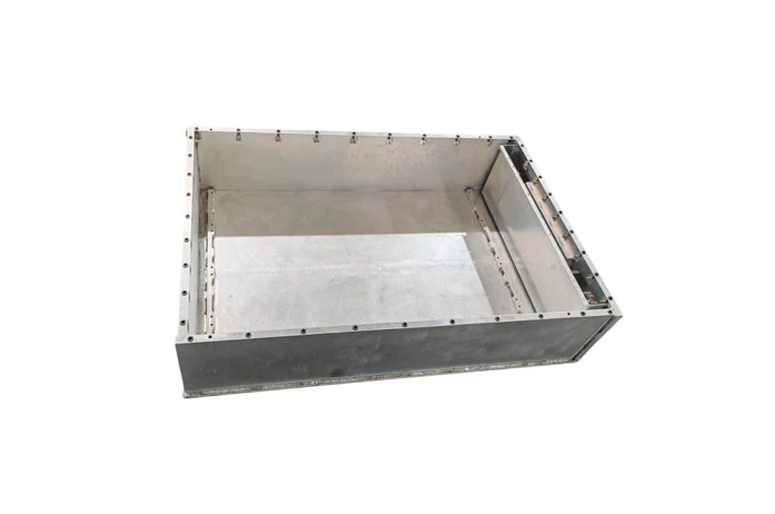
As energy storage systems evolve towards large capacity and high energy density, the size matching and compatibility design of ESS Battery Enclosures have become the core issues for improving system efficiency and reliability. This article combines the latest engineering design cases, patented technologies and industry trends to analyze from three dimensions: space utilization, modular compatibility, and cell arrangement and support design.
1- ESS Battery Pack Enclosure Space Utilization Optimization
The improvement of space utilization of energy storage system integration is essentially a two-way drive of technology iteration and scenario requirements. Through the collaborative innovation of technologies such as large-capacity battery cells, modular architecture, and liquid cooling integration, the industry is moving from "extensive stacking" to "extreme space reuse".
a. Application of large-capacity battery cells: energy density and efficiency leap
Summary of ideas: The application of large-capacity battery cells is essentially to reduce the internal structural level of the battery pack and directly improve the space utilization of the battery cell to the battery pack. Traditional battery packs adopt a three-level integration mode of "battery cell → module → battery pack", and the module structure (crossbeam, longitudinal beam, bolts, etc.) leads to low space utilization. Large-capacity battery cells can directly skip the module level by lengthening or increasing the volume of the single cell, and use CTP (Cell to Pack) technology to directly integrate the battery cell into the battery pack.
Technical core: Use 600Ah+ ultra-large battery cells to reduce the number of battery cells and connection points, and increase the single cell capacity.
b. Spatial reuse and cost optimization: from "component stacking" to "multi-dimensional reuse"
Summary of ideas: Spatial reuse and cost optimization are two sides of the same coin, and their underlying logic is to break the physical and cost boundaries of traditional energy storage systems through structural simplification, functional integration, material iteration and standardized design.
The core of spatial reuse is to reduce the intermediate links through the extreme simplification of the structural level. For example: the two-in-one design of the high-voltage box: Jiangsu Trina Energy Storage's patented technology combines two high-voltage boxes into one, sharing the total positive/negative relay and electrical connection, reducing the horizontal space occupancy by 30%, and reducing the cost of electrical components by 15%.
Cross-domain reuse of functional modules, integration of structural parts and heat dissipation channels, such as integrating the liquid cooling plate with the bottom plate of the box, and sharing the space between the liquid cooling pipe and the structural support, reducing 15% of independent heat dissipation components; the battery body as a structural part: BYD's blade battery provides support strength through the long and thin side walls of the battery cell, eliminating the module frame, and increasing the space utilization rate to 60%-80%.
Deep optimization of electrical topology, for example, high-voltage cascade topology reduces the number of parallel circuits by increasing the capacity and voltage level of single cells (such as Huawei's smart string energy storage), reducing the physical space of the battery stack by 20%, and shortening the system response time by 50%. Shared relay design, Jiangsu Trina Energy Storage's two-in-one high-voltage box allows two lines to share the same relay, reducing the number of relays and cable length by 50%, and improving installation efficiency by 30%.
2- Cell arrangement and support design: load-bearing, heat dissipation and vibration resistance balance
The essence of cell arrangement is the game between space utilization, heat distribution and mechanical stability. The physical form and arrangement direction of the cell directly affect the space filling efficiency:
a. Optimize the arrangement of cells
Inverted cell design: turn the cell explosion-proof valve downward, so that the thermal runaway exhaust and the bottom ball-proof space are shared, releasing the cell height space and achieving volume utilization.
Lying cell layout: optimize the space utilization in the height direction of the battery pack, increase the proportion of active materials, and significantly increase the volume utilization rate than the vertical cell.
Ultra-long and thin cells: reduce the number of cells per unit volume through the cell length and thinness design, and improve the grouping efficiency.
b. Coupling design of heat dissipation and load-bearing: aims to achieve dual optimization of efficient heat dissipation and structural strength through collaborative innovation of structure, materials and processes.
Structural design path:
Integrated structure, such as conformal design of liquid cooling plate and support beam: embed the liquid cooling channel into the aluminum alloy support beam to reduce independent components and improve space utilization;
Layered and compartmented layout, stacking the battery pack, liquid cooling system, and BMS in layers to reduce the mutual interference between heat flow and mechanical stress;
Bionic mechanics optimization, such as honeycomb/corrugated structure, designing honeycomb or corrugated core layer in the aluminum alloy support frame (such as Mufeng.com patent solution), absorbing vibration energy through deformation, and optimizing the heat dissipation path.
Material innovation path:
Integrated heat conduction and load bearing, such as aluminum alloy composite fiber material (thermal conductivity ≥ 200 W/m·K, strength +30%); intelligent material, phase change filling layer (PCM) absorbs heat and releases slowly, temperature difference ±1.5℃; lightweight damping: elastic silicone cushion absorbs vibration (damping +40%).
Process implementation path:
Precision molding process, such as extrusion molding: used to manufacture aluminum alloy liquid-cooled beams with complex flow channels;
Surface treatment technology, such as generating a ceramic oxide layer on the surface of aluminum alloy to improve corrosion resistance (salt spray test ≥1000h), while enhancing heat dissipation efficiency (surface emissivity increased by 20%);
Intelligent assembly process, dynamic preload adjustment, such as integrating pressure sensors and electric actuators to adjust bolt preload (5-20kN) in real time to avoid overpressure damage to the battery cell.
c. Coordinated design of load-bearing and vibration resistance of the support structure: The support system needs to meet the dual requirements of static load-bearing (battery cell weight + stacking pressure) and dynamic vibration resistance (transportation/earthquake shock).
3- Modularity and compatibility: standardized interface and scalable architecture
The essence of standardized interface adapting to multi-size batteries is to achieve flexible expansion of battery specifications on a unified platform through collaborative innovation in mechanical, electrical and thermal management. The current technology has shifted from static compatibility to dynamic adjustment, and will evolve towards intelligence, lightweight and cross-scenario integration in the future.
a. Collaborative innovation of mechanical structure:
Standardization of mechanical interface: define unified connection device size.
Modular battery pack/cabinet design: build scalable modules and battery cabinets through standardized size battery cells (such as 280Ah, 314Ah batteries), supporting flexible combinations of different capacity requirements.
Figure 1-280Ah ESS Battery Pack Enclosure
b. Dynamic adjustment of electrical system
Standardized communication protocols and interfaces, such as BMS compatibility: formulate a unified BMS (battery management system) communication protocol to support seamless connection with PCS and battery cells of different manufacturers; dynamic power adjustment, through virtual inertia control and multi-time scale optimization algorithm, to achieve real-time adjustment of active/reactive power; and adaptive electrical parameter matching design.
c. Intelligent adaptation of thermal management system
Graded thermal management solutions, such as the use of flame-retardant high-rebound foam, thermal conductive glue and other materials at the battery level to balance the insulation and heat dissipation requirements and inhibit heat diffusion; the integrated design of the module-level integrated liquid cooling plate and the insulation layer to improve the cycle life; the system level dynamically adjusts the cooling capacity through variable frequency compressors and multiple cooling branches.
Intelligent monitoring and prediction, multi-sensor fusion. Arrange temperature sensors at key locations such as battery poles and large surfaces to achieve high-precision temperature acquisition; digital twin technology optimizes the heat dissipation strategy in real time through cloud monitoring and predictive maintenance.
4-Summary
The optimization of ESS Battery Enclosure space has shifted from single structural improvement to multi-dimensional collaborative innovation:
The fusion of materials, structure and algorithm, such as the combination of carbon fiber enclosure + CTP technology + AI layout algorithm, will become the mainstream.
Modularization and standardization are accelerating, and the standardized design with Pack as the smallest functional unit will promote the industry to reduce costs and increase efficiency.
The deep binding of thermal management and space utilization, immersion liquid cooling and dynamic temperature control technology further release the potential of space.
For more information on cost control of ESS battery pack enclosures, please read the following article:Lightweight design of ESS Battery Enclosure: analysis of material selection and full-cycle cost control
We will regularly update you on technologies and information related to thermal design and lightweighting, sharing them for your reference. Thank you for your attention to Walmate.
With the explosive growth of AI computing power and the continuous increase in power density of data centers, traditional air cooling technology can no longer meet the heat dissipation needs. Liquid cooling technology has become a must with its advantages of efficient heat dissipation, energy saving and consumption reduction. In liquid cooling technology, the competition between cold plate and immersion cooling is particularly fierce. This article will analyze the advantages and disadvantages of the two from the perspectives of technical characteristics, application scenarios, cost-effectiveness and future trends, and explore their future dominant directions.
1- Cold plate vs Immersion cooling: cold plate type has strong compatibility, and immersion type has higher heat dissipation efficiency
a. Cold plate liquid cooling: a "reformist" with smooth transition
Strong compatibility: No need to significantly modify the server structure, it is compatible with the infrastructure of the existing air-cooled data center, with low modification cost and short cycle.
High safety: The coolant does not come into direct contact with electronic components, the risk of leakage is low, and the risk can be further reduced through modular design (such as quick-change joints and redundant pipes).
High maturity: Cold plate liquid cooling has been widely used in scenarios such as Alibaba Cloud Qiandao Lake Data Center and Intel cooperation projects, accounting for 90% of the current liquid cooling market.
Limitations: The cold plate liquid cooling can only cover some high-power components (such as CPU and GPU), and the rest of the heat still needs to rely on air cooling to assist heat dissipation. The PUE value is usually 1.1-1.2, slightly higher than the immersion type.
b. Immersion cooling: an "innovator" with efficient heat dissipation
Immersion cooling completely immerses the server in insulating coolant, and achieves full device heat dissipation through direct contact. Its core advantages include:
Extreme energy efficiency: The thermal conductivity of liquid is 20-30 times that of air, PUE can be as low as 1.05, and the heat dissipation efficiency is increased by more than 3 times.
Space saving: The volume of the cooling system is only 1/3 of that of air cooling, and the power density of a single cabinet can reach more than 50kW, which is suitable for high-density scenarios such as AI supercomputing.
Silent and environmentally friendly: No fans are required, noise is reduced by more than 90%, and there is no dust pollution, which extends the life of the equipment.
Challenges: Immersion requires customized servers, the cost of coolant accounts for up to 60% (such as fluorinated liquid), and the initial investment is high, and the ecological compatibility needs to be improved.
2-Differentiation of application scenarios: medium- and short-term cold plate dominates, long-term immersion cooling potential is released
a. Cold plate cooling: "cost-effective choice" for stock transformation and new IDC construction
Renovation of old data centers: Cold plate cooling can quickly adapt to the existing air-cooled architecture, with a short transformation cycle and controllable costs. For example, the modular solution cooperated by Intel and Bih reduces the difficulty of deployment through standardized cold plate design.
Medium and high density computing power scenarios: Cold plate cooling already supports 130-250kW power per cabinet (such as NVIDIA B series GPU), meeting most AI training needs.
Data center liquid cold plate-micro channel high-efficiency heat dissipation
b. Immersion cooling: "ultimate solution" for supercomputing and green data centers
Ultra-high density computing power: The cabinet power of the next generation of chips (such as NVIDIA Rubin series) will exceed 1000kW, and immersion cooling will become the only feasible solution.
Green energy-saving needs: The PUE of immersion cooling is close to 1.05, and the waste heat recovery efficiency reaches 90% (such as Lenovo's solution), which is in line with the "dual carbon" target policy.
Immersion cooling of server
c. Current liquid cooling market situation
Cold plate cooling dominates the current market: In 2025, cold plate accounts for 80%-90% of the liquid cooling market, and immersion cooling accounts for less than 10%. In addition, standardized interfaces have been formed (such as Intel's OCP cold plate design), and solutions from manufacturers such as Inspur and Sugon have strong compatibility. The domestic "East Data West Computing" project requires that the PUE of new data centers be ≤1.25, and cold plate cooling has become the first choice for transition.
Immersion cooling is ready to go: Sugon Digital C8000 phase change immersion solution achieves PUE 1.04, and Alibaba Cloud's "Kirin" data center verifies the feasibility of single-phase immersion.High-power chips such as NVIDIA B200 GPU (1000W+) force immersion cooling applications, and liquid cooling computing power density increases by 30%-50%.The EU plans to ban fluorinated liquids in 2028, and domestic hydrocarbon/silicone oil coolant research and development is accelerating (such as Sinopec's "Kunlun" series).
3-Authoritative opinion PK
Cold plate faction: Cold plate is the "icebreaker" of liquid cooling popularization, and will still bear 80% of the incremental liquid cooling market in the next five years. Immersion cooling needs to wait for the chip power consumption to break through the critical point.
Immersion faction: Phase change immersion is the ultimate form of liquid cooling, and cold plate is only a transitional solution. When the power consumption of a single chip exceeds 800W, immersion will become the only choice.
Neutral faction: The differentiation of technical routes reflects the stratification of computing power demand. Cold plate serves "Eastern Data" and immersion supports "Western Computing". Dual-track parallel development will be the main theme for the next ten years.
4-Liquid industry opportunities and strategies
Cost and ecological game: Cold plate has a short-term advantage, and immersion cooling needs to reduce costs to break the deadlock.
Cold plate cooling: Optimize materials (copper-aluminum composite), improve processing accuracy (leakage prevention process), and promote modular and standardized design.
Immersion cooling: Develop cost-effective coolants (such as single-phase immersion liquid), compatible cabinets, and cooperate with chip manufacturers to customize cooling solutions.
Technical reserve: Explore two-phase flow cold plate and intelligent monitoring system (such as AI dynamic flow adjustment) to cope with future high power demand.
5-Conclusion
Short term (2025-2027): Cold plate cooling dominates general scenarios, and immersion cooling penetration rate increases to 15%-20%; Long term (2030+): Phase change immersion cooling becomes mainstream in the field of high computing power, and cold plate retreats to the medium and low density market.
Winning hand: Coolant cost, chip power consumption jump speed, international environmental protection policy.
Click to learn about the development of AI server cooling methods and liquid cooling solutions:The underlying logic of AI server heat dissipation: How does liquid cooling technology cope with the surging heat dissipation demand?
We will regularly update you on technologies and information related to thermal design and lightweighting, sharing them for your reference. Thank you for your attention to Walmate.
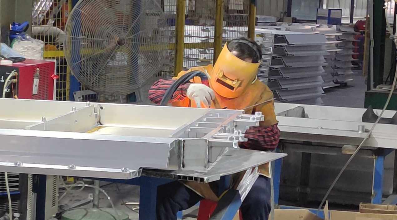
With the rapid development of new energy vehicles and energy storage industries, lightweight, high safety and efficient thermal management have become core demands. Our company is deeply engaged in the field of aluminum alloy material processing. Relying on advanced material selection, forming process and welding technology, we focus on the research and development and manufacturing of battery trays, liquid cooling plates, energy storage pack boxes and radiators. Aluminum alloy has become an ideal choice for lightweight and thermal management of new energy equipment due to its low density (about 2.7g/cm³), high strength, corrosion resistance and excellent thermal conductivity (thermal conductivity is about 150-220 W/m·K).
1- Aluminum alloy material selection and key considerations
Different products have significantly different performance requirements for aluminum alloys, and it is necessary to combine strength, corrosion resistance, weldability and process adaptability to comprehensively select materials:
a. Battery tray
Common grades: 6061-T6, 6005A-T6, 6063-T6.
Selection basis:
·Must meet the tensile strength ≥ 240 MPa (such as 6061-T6) to pass the national standard extrusion, drop and ball impact tests;
·High weldability requirements, thermal cracks must be avoided (Mg/Si-strengthened 6xxx series is preferred);
·Corrosion resistance is improved by anodizing or aluminum cladding.
Figure 1- Aluminum Alloy Battery Tray
b. Energy storage pack box
Common brands: 5083, 6061-T6 (both strength and corrosion resistance).
Selection basis:
·Need to withstand vibration and impact loads, yield strength must be ≥200 MPa;
·High surface treatment requirements to avoid electrochemical corrosion.
c. Liquid cooling plate
Common brands: 3003, 6061/6063, 6082.
Selection basis:
·High thermal conductivity and corrosion resistance;
·Liquid cooling channel requires complex molding, and 6xxx series with excellent extrusion performance are preferred.
2- Differences in process performance and processing difficulties
The processing of aluminum alloys needs to adapt to their physical properties, especially in cutting, CNC, welding and surface treatment:
a. Cutting and CNC processing
Difficulties:
· High-precision hole processing is prone to burrs or deformation (such as protrusions on the edge of step holes) due to material ductility;
· Thin-walled structures (such as liquid cooling plate flow channels) need to control cutting forces to prevent warping.
Solution:
· Use diamond-coated tools to improve edge sharpness and reduce extrusion deformation;
· Optimize processing parameters (such as high speed and low feed) and cooperate with general CNC equipment to achieve stable processing.
b. Welding process
Core challenges:
· Oxide film (Al₂O₃ melting point 2050℃) hinders fusion and easily leads to pores and slag inclusions;
· Some alloys have a high tendency to hot cracks, and the line energy and welding wire composition need to be controlled.
Preferred processes:
·TIG welding (AC power supply): suitable for thin plates, and the oxide film is removed by "cathode cleaning";
·MIG welding (high current + helium mixed gas): high welding efficiency for thick plates, and controllable heat input.
Figure 2- Battery tray welding
c. Surface treatment
·Insulation pressure-resistant coating: Applied to the battery tray and the inside of the Pack box, it must pass the pressure test (≥3000V DC/1min), the coating thickness is 20-50μm, to ensure the insulation safety under high-voltage environment;
·Insulation and dehumidification coating: For the energy storage Pack box, hydrophobic materials (such as fluorocarbon resin) are used to reduce the risk of internal condensation, and the dyne value is ≥34 to ensure adhesion;
·Anti-collision protection coating: used for the outer wall of the battery tray, polyurethane elastomer (hardness ≥80 Shore A) is selected, and the impact resistance is improved by more than 30%;
·Anodizing: Conventional anti-corrosion treatment, film thickness error ≤3μm, suitable for complex structures.
3- Verification inspection and equipment adaptability
In order to meet the standards of the new energy industry (such as GB/T31467.3, UL2580), multi-dimensional verification and process adaptation are required:
a. Verification inspection
· Structural strength: Verify the load-bearing, extrusion and ball impact performance of the tray through finite element simulation (maximum stress ≤ material yield strength);
· Sealing test: The liquid cooling system uses helium leak detection (leakage rate ≤1×10⁻⁶ mbar·L/s) and cyclic pressure test (0.5-1.5MPa/5000 times);
· Coating performance verification:
Insulation coating withstand voltage test (5000V DC/60s without breakdown);
Anti-collision coating passes falling ball impact (1kg steel ball 1m height) and salt spray test (1000h without peeling).
b. Equipment adaptability optimization
· General CNC equipment transformation: Through high-precision fixture design and dynamic compensation algorithm, the processing deformation of thin-walled parts can be ≤0.1mm;
· Welding parameter library: Establish standard welding parameters (such as current and wire feeding speed) for different aluminum alloy grades to reduce the debugging cycle;
· Automated coating spraying: Use multi-axis robot spraying, combined with infrared curing technology, the coating uniformity error is ≤5%.
Conclusion
The wide application of aluminum alloys in new energy equipment is not only a victory of materials science, but also a manifestation of process innovation. Our company will continue to explore new aluminum alloys that are high-strength, corrosion-resistant, and easy to process, and promote the performance upgrade of products such as battery trays and liquid cooling plates through process innovation, helping the industry move towards an efficient and lightweight future.
We will regularly update you on technologies and information related to thermal design and lightweighting, sharing them for your reference. Thank you for your attention to Walmate.
As the power density of electronic devices continues to rise, heat dissipation design has become a key link affecting system reliability and lifespan. As a professional manufacturer with 19 years of experience in thermal management, we combine typical engineering cases with multi-physics field simulation experience to deeply analyze the five major technical misunderstandings that engineers tend to overlook in high-power scenarios, and provide solutions that conform to industry practices.
Misunderstanding 1: Abuse of high thermal conductivity materials, calculation deviation of interface thermal resistance
Typical problem: Excessive pursuit of theoretical values of thermal conductive materials, ignoring the engineering reality of interface contact thermal resistance.
Case analysis: A certain automotive laser radar heat dissipation module uses a pure copper substrate (thermal conductivity 401W/m·K), but the coating thickness of the thermal interface material (TIM) is not accurately controlled (designed 0.1mm, actual fluctuation ±0.05mm), and the measured contact thermal resistance reaches 0.6°C·cm²/W, causing the FPGA junction temperature to exceed the standard by 22%. After switching to preformed thermal pads (tolerance ±0.02mm, thermal resistance <0.03°C·cm²/W) and combining with vacuum sintering process, the junction temperature is reduced by 17°C, and the MTBF (mean time between failures) is increased to 100,000 hours.
Optimization plan:
Material selection: According to the ASTM D5470 standard, the thermal resistance of TIM is measured, and phase change materials or metal-filled elastomers are preferred.
Process control: Use automatic dispensing equipment (accuracy ±3%) to ensure thickness tolerance <10% and avoid air gaps.
Misunderstanding 2: Mismatch of airflow organization in air cooling system, local hot spots out of control
Typical problem: blindly stacking the number of fans, ignoring the flow channel impedance matching and boundary layer separation effect.
Engineering example: A data center GPU cluster uses 4 12038 fans (air volume 200CFM), but due to improper design of the air guide angle (90° right angle bend), the actual effective air volume is only 65% of the nominal value, and the local temperature difference reaches 40°C. After CFD simulation optimization, the air guide is changed to a gradually expanding flow channel (diffusion angle <7°), and a staggered fin layout is adopted (the spacing gradient increases from 2mm to 3.5mm), the overall wind resistance is reduced by 30%, and the hot spot temperature difference is controlled within 8°C.
Core strategy:
Flow field design: Wind tunnel testing is carried out according to ISO 5801 standard to optimize the inlet and outlet area ratio (recommended 1:1.2).
Dynamic control: Based on the Q-H curve of the PWM fan, the system impedance point is matched to the highest efficiency range (usually 60-80% of the maximum air volume).
Misconception 3: Failure of environmental protection design accelerates material aging
Typical problem: Only focusing on initial heat dissipation performance, ignoring the effects of long-term environmental stress such as humidity, heat, dust, and salt spray.
Case analysis: An offshore wind power converter uses a 6061 aluminum alloy heat sink (surface anodized). After running in a salt spray environment for 6 months, the oxide layer peeled off, causing the contact thermal resistance to increase by 50%, and the IGBT failure rate to surge. Switching to 5052 aluminum alloy (salt spray resistance >1000h) and spraying polyurethane three-proof paint (thickness 50μm, in line with IEC 60068-2-11 standard), the 3-year field failure rate dropped by 75%.
Design points:
Coating technology: Plasma spraying Al2O3 ceramic coating (thermal conductivity 30W/m·K, temperature resistance >800°C) is used in high-temperature scenarios.
Sealing structure: IP69K protection level (double-pass silicone seal + pressure relief valve) to ensure zero intrusion of dust/water vapor.
Misconception 4: Lack of transient heat load modeling and improper selection of phase change materials
Typical problem: The heat dissipation solution designed by steady-state simulation cannot cope with millisecond-level power pulses.
Measured data: A solid-state power amplifier is subjected to a 2ms@2000W pulse load in a 5G base station. The transient temperature rise of the traditional aluminum substrate solution reaches 55°C, while the microcapsule phase change material (paraffin/graphene composite, phase change latent heat 220J/g) combined with transient thermal simulation (ANSYS Icepak transient step length 1ms) is used to control the temperature rise to 18°C, meeting the MIL-STD-810G impact test requirements.
Dynamic management technology:
Phase change packaging: The honeycomb structure is used to encapsulate the phase change material (porosity>70%) to avoid liquid leakage and improve heat diffusion efficiency.
Model calibration: The simulation boundary conditions are corrected based on infrared thermal imaging (sampling rate 100Hz), and the error is <±1.5°C
Misconception 5: TCO evaluation is one-sided and ignores hidden operation and maintenance costs
Typical problem: Only the initial hardware cost is compared, and the energy consumption/maintenance/downtime losses are not quantified.
Cost comparison: A semiconductor factory originally used air-cooled cabinets (initial cost of 500,000 yuan), with an annual electricity bill of 1.2 million yuan (PUE=1.8). After upgrading to two-phase immersion liquid cooling (initial cost of 1.8 million yuan), the annual electricity bill dropped to 450,000 yuan (PUE=1.05), and due to the reduction of clean room air conditioning load, the annual comprehensive savings reached 900,000 yuan, and the incremental investment can be recovered in 2.1 years (IRR>25%).
Decision model:
Refined modeling: Introduce Monte Carlo simulation to quantify the impact of equipment failure rate (Weibull distribution) on TCO.
Policy superposition: Combined with carbon tax mechanisms (such as EU CBAM), the carbon emissions of liquid cooling systems over their entire life cycle are reduced by 60%, and an additional subsidy of 15% is obtained
Conclusion: Upgrading the thermal design paradigm from experience-driven to data-driven
Standardized process: Introduce the JESD51-14 thermal test standard in the conceptual design stage to avoid rework later (the project cycle of a certain optical module is shortened by 30%).
Multidisciplinary collaboration: Through COMSOL Multiphysics coupling electromagnetic loss (HFSS extraction) and thermal strain field, the heat dissipation efficiency of a radar TR component is improved by 40%.
Intelligent operation and maintenance: Deploy fiber grating temperature sensors (accuracy ±0.1°C) and digital twin platforms to achieve fault prediction (unexpected downtime of a supercomputing center is reduced by 90%).
Through rigorous engineering thinking and full-link data verification, thermal design engineers can accurately avoid "invisible killers" and lay the foundation for high-reliability systems. As industry practitioners, we are committed to providing closed-loop solutions from materials to systems, and jointly address thermal management challenges with customers.
We will regularly update you on technologies and information related to thermal design and lightweighting, sharing them for your reference. Thank you for your attention to Walmate.
1- Special tolerance requirements for key parts
In the manufacturing of EV battery trays and Liquid Cooling Energy Storage Battery Pack Enclosure, the tolerance control of key connection surfaces and interfaces directly affects the sealing, heat dissipation efficiency and assembly accuracy.
a. Liquid cooling plate installation surface
The liquid cooling plate is the core component of the battery thermal management system. The flatness of its installation surface directly affects the sealing of the coolant flow channel. If the flatness is out of tolerance, it will cause uneven compression of the silicone gasket, causing local leakage or increased thermal resistance.
b. Welding seam misalignment
The battery tray often uses an aluminum alloy welding structure. Welding seam misalignment will cause stress concentration and reduce fatigue life. Especially for scenarios with high requirements for Battery Pack Enclosure airtightness (such as IP67), misalignment must be strictly controlled.
c. Battery module positioning hole
The positioning hole is used to accurately fix the battery module. Excessive tolerance will cause module misalignment, causing electrical connection failure or mechanical vibration risks.
d. Fixing bolt hole position
The bolt hole is used to connect the Battery Pack Enclosure to the chassis. Position deviation will cause assembly stress and even cause bolt breakage.
e. Battery Pack Enclosure edge straightness
The Battery Pack Enclosure edge straightness affects the assembly of the upper and lower covers and the IP protection level, especially for laser-welded enclosures, where the edge needs to be used as a reference for laser head tracking.
2-The impact of dimensional tolerance on manufacturing efficiency
The impact of dimensional tolerance on manufacturing efficiency is mainly reflected in its balance between processing flow, cost control and product quality. Reasonable tolerance design can not only ensure product function, but also optimize production rhythm. The impact of reasonable control of dimensional tolerance on manufacturing efficiency is mainly reflected in the following aspects:
a. Balance between processing accuracy and production cost
· Although strict dimensional tolerance can improve sealing and assembly accuracy, high-precision processing equipment and complex processes are required, which significantly increases equipment investment and processing time.
· Excessive pursuit of accuracy may lead to increased processing costs. Strict tolerances need to be set in key functional parts, and tolerances should be appropriately relaxed in non-critical areas to reduce costs.
b. Control of rework rate and scrap rate
· Reasonable tolerance design can reduce rework caused by dimensional deviation.
· Welding deformation is the main problem in battery tray manufacturing. The use of CMT cold welding process can optimize heat input, reduce deformation after welding, and shorten the rework cycle.
c. Modular and standardized production
· Through standardized components, tolerance requirements are concentrated on local replaceable parts, reducing the overall processing difficulty.
· Standardized tolerance design can also support multi-model compatibility and reduce the need for customized processing.
3-Industry standards and practical applications of flatness control
For new energy vehicle battery trays, industry standards have strict requirements:
a. Flatness standard: The flatness of the liquid cooling plate installation surface must be ≤0.2mm, the flatness of the bottom support plate must be ≤0.5mm/m², and the flatness error of the frame after welding must be ≤0.8mm6.
b. Manufacturing process optimization: CNC precision milling, CMT cold welding and vibration aging treatment (VSR), combined with laser interferometer online detection, reduce the risk of deformation.
c. Material selection: It is recommended to use high-strength aluminum alloys such as 6061, with a yield strength of ≥1180MPa, taking into account both lightweight and structural stability.
4- Tolerance adjustment strategy driven by materials and processes
a. Material innovation drives lightweighting
Using lightweight high-strength aluminum alloys (such as 6061) and composite materials (silicon carbide reinforced aluminum matrix), combined with anodizing and insulating coating, to achieve 30% weight reduction and improve corrosion resistance, adapting to the heat dissipation requirements of liquid cooling systems.
b. Process collaboration improves manufacturing accuracy
One-piece extrusion molding + stir friction welding (FSW) reduces the number of welds, CMT cold welding and laser welding control thermal deformation.
c. Simulation detection closed loop to ensure reliability
CAE simulation optimizes the layout of reinforcement ribs, laser scanning and helium leak detection technology realize full process monitoring, modular design is compatible with ±5mm tolerance, reducing costs and increasing efficiency.
We will regularly update you on technologies and information related to thermal design and lightweighting, sharing them for your reference. Thank you for your attention to Walmate.
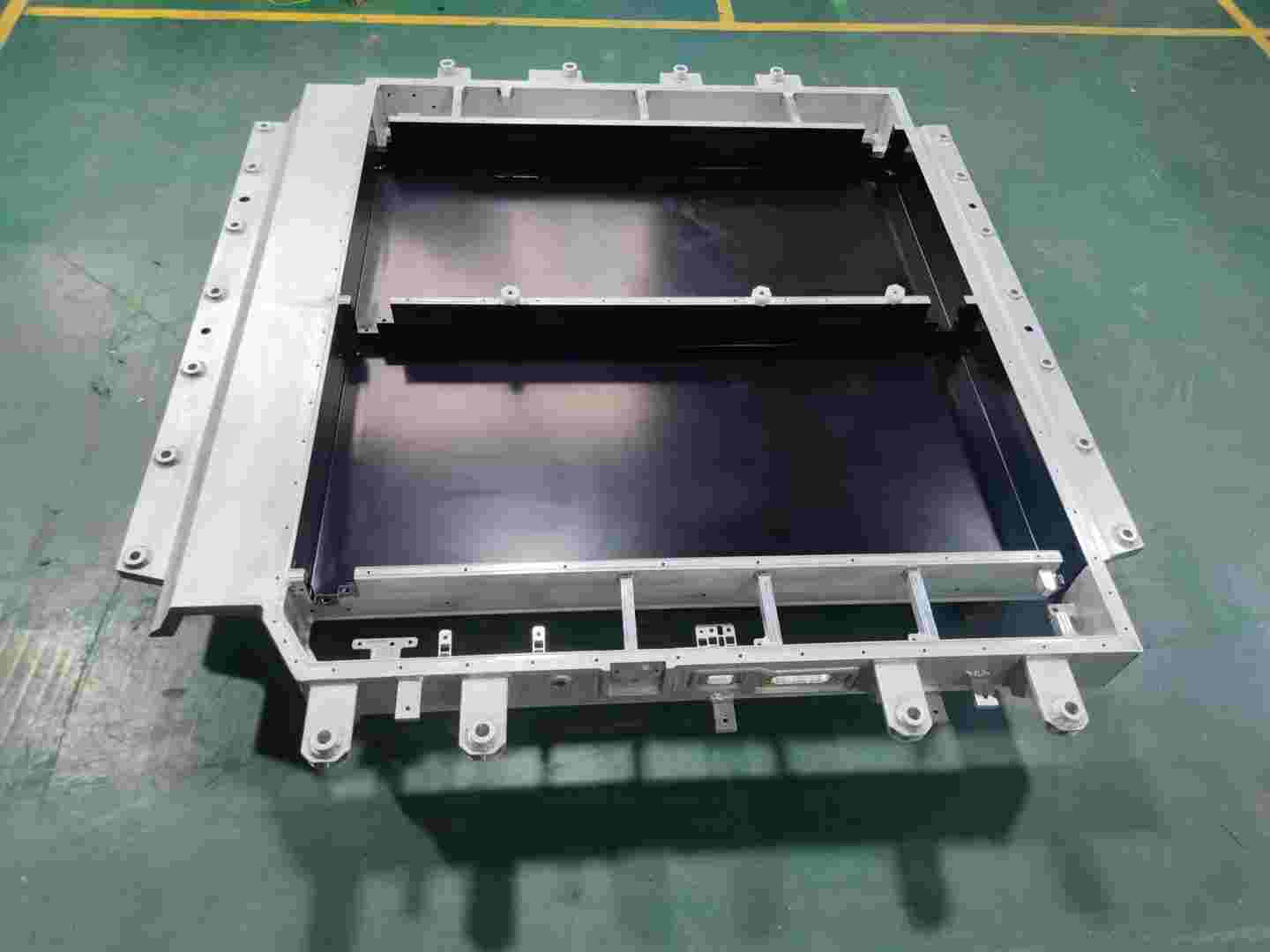
1- Battery tray / energy storage pack box aluminum alloy welding process characteristics
In the manufacturing of new energy liquid-cooled Pack boxes, battery trays and other products, liquid cooling channels and multi-cavity structures are typical complex design features (as shown in Figure 1). Such structures often include the following features:
Figure 1: Typical design of a battery tray
Three-dimensional space interlacing: the flow channels are distributed in a serpentine shape, with a large number of spatial turning points;
Multi-level connection: the main cavity and sub-cavity are connected by thin-walled partitions (thickness 2-3mm);
Miniaturization features: small flow channel cross-section size (the minimum wall thickness of the aluminum profile flow channel is 1.2mm) and poor welding accessibility.
2- Difficulty analysis of combining multiple welding technologies in battery tray manufacturing
In the practice of battery tray manufacturing, it is necessary to combine multiple welding technologies, such as the coordinated application of friction stir welding (FSW), cold metal transition welding (CMT), traditional melting welding (TIG/MIG) and other technologies. This combination aims to take into account lightweight, strength, sealing and production efficiency, but it also faces the following core difficulties:
a. The problem of coordinated heat input of multiple processes
Different welding technologies (such as FSW and laser welding) have large differences in heat input, which can easily cause material performance mutations and thermal deformation, and need to be solved by optimizing the welding sequence and parameter adjustment.
b. Equipment compatibility and efficiency bottleneck
Equipment switching is complex and parameter synchronization accuracy requirements are high. Modular workstation design and intelligent welding machines are required to improve collaborative efficiency and reduce cycle time.
c. Challenges of balancing sealing strength and cost
The risk of leakage at the intersection of multiple welds is high (accounting for 70% of defects), and redundant sealing + topology optimization design is required.
3-Engineering practice: Battery tray, energy storage liquid cooling PACK box multi-welding process coordination
a. Weld scar position planning
· Welding position optimization: In the product design stage, the rationality of the welding position should be fully considered to avoid weld scars appearing in key parts or areas that affect product functions. For example, adjust the gap between the front frame and the water nozzle to prevent weld scar interference; optimize the welding position of the water nozzle to reduce the impact on product performance.
· Matching with product structure: The welding position should match the product structure to ensure that the weld can withstand various loads and stresses during the use of the product. For example, in the liquid cooling plate project, the structural stability and reliability of the product are improved by rationally planning the welding position.
· Easy to operate and detect: The welding position should be convenient for operators to perform welding operations and subsequent quality inspections. For example, avoid welding in locations that are difficult to reach or have poor visibility to improve welding efficiency and quality.
b. Weld scar control
· Weld scar size: The size of the weld scar needs to be strictly controlled. Generally, the weld scar height is required to be within the range of 4/6mm, and the weld scar does not exceed the plane to ensure the appearance and assembly accuracy of the product. For example, in the liquid cooling plate project, the size of the weld scar was successfully controlled by adjusting the welding parameters and process, avoiding the impact of the weld scar on product performance and quality.
· Weld scar shape: The weld scar shape should be as regular as possible to avoid excessive melting or incomplete fusion. By optimizing welding parameters and operating techniques, the weld scar shape can be effectively improved and the weld quality can be improved.
· Grinding treatment: For the concave weld marks produced at the friction welding position, grinding treatment is used to ensure a smooth surface to meet the product appearance and performance requirements.
c. Welding sequence optimization
· Partition welding: For large products, the method of partition welding can effectively control the overall deformation. By dividing the product into several areas and welding them in sequence, the heat concentration during the welding process can be reduced and the risk of thermal deformation can be reduced.
· Step-by-step correction: During the welding process, the step-by-step correction method is used to adjust the welding deformation in time. By continuously measuring and correcting the deformation of the product during the welding process, the dimensional accuracy and shape of the final product are ensured to meet the design requirements.
· Optimize the welding path: Rationally plan the welding path to avoid repeated welding in the same area and reduce heat input. For example, in the liquid cooling plate project, the heat input during the welding process was reduced and the welding quality was improved by optimizing the welding path.
d. Deformation collaborative control
The liquid cooling plate undergoes thermal deformation during the welding process, resulting in a decrease in the dimensional accuracy of the product.
Optimization measures:
· Use partition welding and step-by-step correction methods to control the overall deformation.
· Optimize welding parameters, reduce current and voltage, and reduce heat input.
· Use fixtures to fix the product to reduce movement and deformation during welding.
Use symmetrical welding method to make welding heat evenly distributed.
We will regularly update you on technologies and information related to thermal design and lightweighting, sharing them for your reference. Thank you for your attention to Walmate.
CTC (Cell-to-Chassis) technology has attracted much attention because it can significantly improve the range and space efficiency of electric vehicles, but whether it can truly replace traditional battery technology is still controversial. The core bottleneck on the manufacturing side - the battery tray welding process - has become the key to determining the future of this technology: complex structural design, multi-material compatibility, and stringent thermal management requirements have put traditional welding technology to a huge test. Starting from the perspective of front-line engineers, combining industry trends and engineering practices, this article analyzes the potential and limitations of CTC technology, and explores how welding technology has become the "touchstone" of this technological revolution.
1-The "Ideal and Reality" of CTC Technology
CTC technology can theoretically reduce redundant structural parts and improve energy density by integrating the battery cell directly into the chassis, but the feasibility of its large-scale application is facing realistic challenges:
Car companies' radicalism and caution: Tesla, BYD and other leading companies have launched CTC solutions, but more manufacturers are still waiting and watching. Industry data shows that as of February 2025, CTC mass-produced models account for 15-20% of the world, and traditional CTP (Cell-to-Pack) technology is still the mainstream.
The "cost" of improved battery life: Although CTC can increase energy density by 15%-20%, the complexity of the chassis structure leads to an increase in manufacturing costs of 30%-50% (calculated by a consulting agency), and the balance between cost and benefit is not yet clear.
Maintenance economic controversy: The integrated design has caused the battery maintenance cost to soar. Insurance company data show that the replacement rate of battery assemblies after accidents of CTC models is as high as 70%, far higher than the 25% of traditional models.
These contradictions make the future of CTC technology full of variables. Whether the market can break through 20% depends on three major variables: the progress of Tesla Cybertruck mass production; whether the price war among Chinese automakers forces CTC to reduce costs; and the degree of compromise of European regulations on battery repairability. The level of welding technology on the manufacturing side will be the key to determining whether it can cross the gap between laboratory and mass production.
2-Three "life and death barriers" of welding process
For battery tray manufacturers, the implementation of CTC technology needs to overcome three core problems:
a. The game between "micron-level" precision and efficiency
Traditional welding processes can tolerate 0.5mm errors, but CTC trays need to carry more batteries, and the number of seams increases by more than 3 times, and most of them are distributed on curved and irregular parts. Tests by a manufacturer show that when the welding positioning error exceeds 0.15mm, the yield rate of battery cell assembly will drop sharply from 99% to 82%. What's more tricky is that the improvement in precision is often accompanied by a decrease in efficiency-although the accuracy of laser welding is high, the equipment cost is more than 5 times that of traditional welding.
b. The "water and fire" of mixed materials
In order to balance lightweight and strength, CTC trays often use a mixed structure of "aluminum alloy + carbon fiber + special steel". The difference in thermal expansion coefficients of different materials can be up to 20 times (such as aluminum 23μm/m·K vs. carbon fiber 0.8μm/m·K), which is easy to generate internal stress during welding and cause cracking. When a company tried to connect aluminum and carbon fiber, the crack rate of the weld was as high as 18%, far exceeding the industry's acceptable threshold of 3%.
c. "Invisible killer" of the heat-affected zone
High welding temperature may damage the insulating materials or sensor circuits around the battery cell. A car company once increased the self-discharge rate of the battery module by 50% due to improper control of welding heat input. Engineers must control the welding temperature fluctuation within ±15℃ within 0.1 seconds - this is equivalent to installing a "high-precision temperature brake" on the welding gun.
3-The way out: There is no silver bullet, only system innovation
Faced with these challenges, the industry is exploring three breakthrough paths:
a. "Cocktail therapy" of process combination
Laser arc hybrid welding: Combining the accuracy of laser welding with the advantages of arc welding penetration, the welding speed of aluminum alloy is increased by 40%;
Cold metal transition technology (CMT): Through precise heat input control, the area of heat affected zone is reduced by 60%;
Robot intelligent compensation system: Automatically adjust the welding gun path based on real-time weld scanning data, and increase the qualified rate of complex curved surface welding from 75% to 95%.
b. "Pre-compromise" on the material side
Some companies have begun to jointly develop "welding-friendly" composite materials with material suppliers. For example, the welding crack sensitivity of a domestic modified aluminum alloy (aluminum alloy material adjusted by physical, chemical or process means) has been reduced from level 7 to level 3 (according to ISO standards). Although it sacrifices 5% of the lightweight effect, it increases the welding yield to 98%.
4- Engineers’ new proposition: Finding certainty in uncertainty
a. The controversy over CTC technology is essentially a game between “system optimization” and “local limits”:
If the breakthrough speed of welding process is slower than the cost reduction expectations of car companies, CTC may become a niche technology;
If materials, processes, and testing technologies make breakthroughs in a coordinated manner, it is expected to usher in a new era of electric vehicle structural design.
b. For engineers, it is necessary to reconstruct capabilities from two dimensions:
Cross-domain knowledge integration: understand the sensitive threshold of electrochemical properties to welding heat input;
Agile response capability: A case study of a European supplier shows that the team that can complete the optimization of welding parameters of new alloy materials within a week has a 3-fold increase in the probability of obtaining orders.
CTC technology stands at the crossroads of “disruptive innovation” and “mass production trap”. It may not completely replace existing technology, but it is forcing the welding process to evolve towards higher precision, stronger compatibility, and more intelligent control. In this technology marathon, the real winner may not be the earliest car company, but the engineering team that turns “impossible welds” into “standardized interfaces” on the manufacturing side.
We will regularly update you on technologies and information related to thermal design and lightweighting, sharing them for your reference. Thank you for your attention to Walmate.

As CTP (Cell to Pack) technology completely subverts the traditional battery pack structure, the "role" of the battery tray has shifted from passive load-bearing to active integration. Welding technology has become the core of safety and performance. The requirements of lightweight (wall thickness is only 1.5mm), zero pore sealing, and multi-material (aluminum/copper/carbon fiber) integration have caused traditional welding to fall into the dilemma of deformation and defects. The industry is making breakthroughs through material innovation, intelligent quality inspection and process iteration. This article will analyze the disruptive challenges that CTP poses to welding and explore the technical path to high precision and high reliability.
1-Analysis of the changes in the structural design requirements of battery trays due to CTP technology
CTP (Cell to Pack) technology directly integrates the battery cells into the battery pack by eliminating the module structure in the traditional battery pack. This technological innovation puts forward all-round and multi-dimensional upgrade requirements for the structural design of the battery tray. The following is a specific analysis from the perspectives of materials, performance, process, integration, etc.:
(1) Comprehensive improvement of structural strength and shockproof performance
a. Mechanical bearing requirements after eliminating the module:
After CTP technology eliminates the module structure, the battery tray needs to directly bear the support, fixation and external force buffering functions of the battery cell. The traditional module disperses the mechanical load, while the CTP tray needs to absorb the expansion deformation of the battery cell during charging and discharging as a whole (for example, the expansion force of the square battery cell can reach 10-20kN), while resisting the vibration, extrusion and impact load during vehicle driving.
b. Material and structural optimization direction
· Dominance of high-strength aluminum alloy: Early steel was gradually replaced due to its heavy weight, and 6061-T6 became the mainstream. It has high specific strength and strong corrosion resistance, which can meet the dual requirements of lightweight and high rigidity.
· Composite structure design: For example, the "double-frame ring beam" structure of Leapmotor enhances local impact resistance through longitudinal and transverse beam compartments, while using extrusion technology to optimize material distribution and reduce redundant weight.
· Exploration of magnesium-aluminum alloy and carbon fiber: Magnesium-aluminum alloy is 30% lighter than traditional aluminum materials, and carbon fiber composite materials have both high strength and lightweight characteristics, but are currently only used in high-end models due to cost and process maturity.
(2) Requirements for integrated air tightness and thermal management
a. Sealing performance upgrade
After the module is removed, the internal coolant circulation and gas sealing of the battery pack are completely dependent on the tray, and welding defects (such as pores and cracks) may lead to leakage risks.
Figure 1-Battery tray air tightness test
b. Integration of thermal management functions
CTP trays need to integrate components such as liquid cooling plates and thermal conductive adhesives. For example, structural adhesives are used to fix the battery cells and transfer expansion stress, and polyurethane thermal conductive adhesives (thermal conductivity > 1.5 W/m·K) are used for heat conduction between battery cells and with liquid cooling tubes. The amount of adhesive used in a single PACK is more than 50% higher than that in traditional structures. Flow channels need to be designed inside the tray to optimize cooling efficiency while avoiding damage to the sealing caused by the heat affected zone of welding.
(3) Lightweighting and material innovation
a. Material selection trends
Aluminum alloy extrusion and die-casting process: extruded aluminum profiles are used for frame structures (such as Tesla's 4680 battery tray), and die-casting processes (such as integrated die-casting) simplify the welding process and reduce weight by 15%-20%.
Application of plastic composite materials: For example, glass fiber reinforced PA6 materials are used in non-load-bearing parts to further reduce weight, but the compatibility problem with the metal connection interface needs to be solved.
b. Lightweight design strategy
Topology optimization: Reduce redundant materials through CAE simulation and reduce the weight of the tray while ensuring strength.
Thin-wall and integrated: The wall thickness of the tray is reduced from 3mm to 1.5-2mm, and functional components such as BMS brackets and wiring harness channels are integrated to reduce the number of parts.
(4) Integration and modular design
a. High integration of functional components
CTP trays need to integrate modules such as battery management system (BMS), high-voltage connectors, and fireproof isolation layers.
b. Modular and compatible design
The welding production line needs to support mixed production of multiple models of trays, be able to achieve "one-click change of type", and be compatible with tray structures of different battery cell sizes (such as square and cylindrical).
2-Specific challenges of CTP technology innovation to welding process
CTP (Cell to Pack) technology has significantly improved space utilization and energy density, but it has also posed unprecedented challenges to welding process.
(1) The difficulty of controlling welding defects has increased sharply
a. Porosity and sealing challenges
After CTP technology eliminates the module, the battery tray needs to directly assume the sealing function. Welding pores (a common defect in aluminum alloy welding) will directly lead to the risk of coolant leakage or gas penetration.
b. Cracks and material compatibility
High zinc aluminum alloys (such as 7 series) are prone to cracks due to thermal stress during welding.
c. Gap and assembly error
The direct integration of multiple cells leads to an increase in the number of splicing points of the tray structure. The accumulation of assembly errors may cause the weld gap to exceed ±1mm.
(2) Process adaptation problems brought about by the upgrade of the material system
a. Welding challenges of lightweight materials
The CTP tray material has shifted from steel to aluminum alloy (6061-T6, 7075-T6), magnesium-aluminum alloy (30% weight reduction) and carbon fiber composite materials. Aluminum alloy welding needs to solve the problem of insufficient penetration caused by the difficult melting of the oxide film and high thermal conductivity.
b. Dissimilar material connection technology
When the tray integrates functional components such as liquid cooling plate (copper/aluminum) and fireproof layer (ceramic matrix composite material), brittle intermetallic compounds are prone to appear at the interface of dissimilar materials.
(3) Upgraded structural complexity and precision requirements
a. Deformation control of large-size thin-walled structures
The wall thickness of the CTP tray is reduced from 3mm to 1.5-2mm, and the sensitivity of welding thermal deformation increases sharply.
b. High-density solder joints and process efficiency
The number of solder joints on a single tray has increased from 2,000 in traditional modules to more than 5,000.
Figure 2- Battery tray welding
3-Upgrade of production process and quality control
CTP technology promotes the transformation of battery tray welding from "single process" to "multi-technology collaboration, intelligence, and greening". Manufacturers need to focus on three major directions:
Technology upgrade: break through the control of defects such as pores and cracks, and adapt to lightweight materials;
Intelligent transition: full process digitization and AI quality inspection to achieve high-precision production;
Ecological collaboration: jointly build technical standards with material suppliers, equipment suppliers, and OEMs.
We will regularly update you on technologies and information related to thermal design and lightweighting, sharing them for your reference. Thank you for your attention to Walmate.
On the path toward Exascale AI computing power, Huawei's CloudMatrix 384 Super Node and NVIDIA's GB200 NVL72 cluster have emerged as two globally prominent technological peaks. They not only represent different hardware integration capabilities but also profoundly reveal two fundamental philosophies for building supercomputing systems.
One is metaphorically described as a "sustained high fever," facing the ultimate thermal challenge of densely packed, steady-state heat dissipation from 384 chips operating at full throttle. The other is likened to "intermittent epileptic seizures," requiring the taming of intense, pulsed heat flows generated when 72 top-tier GPUs work in synchrony. These two different "maladies" ultimately lead to entirely distinct "prescriptions"—namely, thermal solutions—and provide us with a clear view of two core engineering philosophies: deterministic systems engineering versus agile ecosystem innovation. For every company in the supply chain involved, understanding this duel is key to defining their future role.
1-The Root of Core Differences – The "Malady" Determines the "Prescription"
From the outset of design, Huawei and NVIDIA embarked on different paths, directly shaping their distinct thermal source characteristics:
Table 1: Comparison of Thermal Source Characteristics Between Two Technical Approaches
The difference between this "sustained high fever" and "intermittent epileptic seizures" is by no means accidental. It reflects Huawei's choice as a challenger to focus on total system performance, pushing the limits of computing density within a single cabinet at all costs, while NVIDIA, as the leader, faces the task of building an ecosystem that can efficiently collaborate and be widely adopted while maintaining an absolute performance advantage per chip.
2- The Materialization of Engineering Philosophy – Two Liquid Cooling Paths
The two distinct design philosophies are most vividly embodied in their respective liquid cooling solutions, shaping the complete technology stack from the chip to the data center room.
a. Huawei: The Liquid Cooling Practice of Deterministic Systems Engineering
This is a top-down design philosophy born for system-level deterministic goals. Its core lies in treating thermal management as a crucial part of the infrastructure, achieving it through globally integrated, highly reliable engineering, rather than treating it merely as a supporting component.
Figure 1: Huawei Ascend 384 Super Node
· Chip-level Precision Engineering and Reliable Connection: To ensure efficient heat transfer from the chip to the cold plate, Huawei focuses on engineering optimization of interface materials. While public information shows its advanced patent reserves in this field (e.g., using high-sphericity silicon carbide fillers), its specific implementation within the super node remains undisclosed. It is certain that its solution inevitably pursues extremely low interfacial thermal resistance and long-term reliability to meet the "sustained high fever" challenge.
· System-level Redundancy and Intelligent Control: Adopts redundant designs, such as ring-shaped liquid supply, and develops in-house Liquid Cooling Thermal Management Units (TMUs) as the system's "central nervous system." This controller enables zero-second switching between pipelines and utilizes AI for failure prediction, ensuring the determinism and reliability of the thermal dissipation chain in a software-defined manner—a hallmark of its systems engineering thinking.
· Infrastructure Convergence ("Cooling-Power Integration"): At the cabinet level, the Liquid Distribution Unit (LDU) and the High-Voltage Power Distribution Unit (PDU) are physically integrated and managed uniformly. This "cooling-power integrated" design is the ultimate engineering response to the ultra-high power density per cabinet, simplifying deployment and improving energy efficiency (lowering PUE). It represents the physical manifestation of its deterministic design philosophy.
b. NVIDIA: The Liquid Cooling Framework of Agile Ecosystem Innovation
This is a design philosophy centered on the GPU, empowering the global ecosystem through the definition of open standards. Its core is to provide a validated "blueprint," lowering the application barrier for the entire industry and enabling efficient, flexible, and large-scale deployment.
· Chip-level Standardization and Reference Design (VRD): NVIDIA provides detailed thermal reference designs for its GPUs (e.g., the Blackwell series), explicitly defining the performance interfaces for the cold plate, including physical dimensions, Thermal Design Power (TDP), flow rate, and pressure drop. This essentially provides a "standard answer" for all cooling vendors, encapsulating complexity within standardized components and ensuring compatibility and a quality baseline for foundational parts.
Figure 2: NVIDIA Server Module and Micro-channel Cold Plate
· Ecosystem-level Collaboration and Solution Certification: Engages in deep collaboration with top thermal management and infrastructure vendors like Vertiv and Boyd to jointly develop and certify cabinet-level liquid cooling solutions. For instance, Vertiv's Tier 2 Ready cabinet solution is a pre-validated product developed based on NVIDIA's blueprint, enabling data center operators to rapidly obtain a plug-and-play liquid-cooled cluster as easily as procuring standard equipment.
· Digital Twin Enablement and Deployment Acceleration: Leveraging the NVIDIA Omniverse platform, it provides digital twin and simulation tools for data center liquid cooling systems. Customers can design, verify, and optimize cooling solutions in a virtual environment, significantly reducing the cost and risk of physical validation and achieving agility from design to deployment.
To understand these two paths more clearly, their core differences are compared below:
Table 2: Huawei Model vs. NVIDIA Model: Key Differences at a Glance
3- Historical Inspiration and Future Convergence
The competition between these two paths is not an isolated case in the history of technology. It is, in essence, another classic enactment of systemic integrated innovation versus platform-ecosystem innovation. Huawei resembles Apple during the Steve Jobs era, pursuing absolute control over the product experience from top to bottom. In contrast, NVIDIA is more like today's Google Android, driving the prosperity of an entire ecosystem by setting core standards (the Android system / GPU architecture).
For the industry, the future trend is not about one side completely replacing the other but likely involves a degree of convergence:
· In national or enterprise-level projects pursuing ultimate computing power, the allure of "Deterministic Systems Engineering" remains undiminished.
· In the vast commercial cloud computing market, "Agile Ecosystem Innovation" will continue to expand due to its speed and cost advantages.
· Sparks of ingenuity may emerge at the intersection: incorporating deeper customization and collaborative optimization within open ecological standards.
4- Conclusion
Therefore, the cooling debate between Huawei and NVIDIA is fundamentally a contest between two core competitive strengths in the AI era: one side pursues deterministic, extreme performance through the deep integration of systems engineering; the other drives agile industry innovation and rapid proliferation by building open standards and ecosystems. This duel delineates clear path choices for participants in the industrial chain: to act as a "spearhead force," deeply integrated and tackling specific system-level fortresses, or to serve as the "main force," integrating into the ecosystem to explore markets across the vast plains of standardization. Ultimately, victory lies not only in the technology itself but also in the insight into the logic of industrial evolution and a clear definition of one's position in the future blueprint.
We will regularly update you on technologies and information related to thermal design and lightweighting, sharing them for your reference. Thank you for your attention to Walmate.
When the "Large" Size of Battery Cells Becomes a Consensus, the "Strength" of the Pack Becomes the New Battleground
The energy storage industry is entering an era of leapfrogging battery cell capacities, with the shift from 280Ah towards 500Ah+ already underway. While the industry focuses on the "largeness" of cells, the "strength" of the Pack—specifically its mechanical structure's load-bearing and safety mitigation capabilities—is becoming the new competitive focus. Regardless of the evolution in cell chemistry and capacity, the resulting expansion forces, thermal runaway energy, and mechanical loads ultimately must be borne by the Pack's lower enclosure, its mechanical foundation.
From a structural design perspective, this article explores how the Pack lower enclosure can address differentiated mechanical and thermal management demands amidst diverging cell technology pathways, and build sustainably adaptable engineering capabilities.
1- Mechanical Analysis of Three Major Technology Paths: The Triangular Challenge of Load, Heat, and Space
The increase in cell capacity directly alters the boundary conditions for Pack system design. As the "skeleton" and "skin" of the system, the lower enclosure must re-address three fundamental questions:
a. Mechanical Analysis for the 587Ah (High-Integration Path)
Core Demand: Achieving energy density ≥6MWh within a standard 20-foot container has spurred ultra-compact layouts like "4 columns, 8 clusters in total."
Lower Enclosure Challenges:
· Structural Load-Bearing Optimization: With increased overall mass but reduced support points, the enclosure must optimize load transfer paths, balancing overall stiffness with local strength in critical areas to ensure structural stability during transportation and operation.
· Integration of Thermal Management Structure: The liquid cooling system is deeply integrated with the enclosure's base plate and support structures, serving both as the thermal management core and participating in overall load-bearing. The design must ensure the long-term reliability of cooling seals under sustained structural loads and thermal cycling.
Simulation of Energy Storage Pack Lower Enclosure
· Precise Spatial Coordination: The enclosure must allocate reasonable clearances within the limited space for cell expansion, thermal displacement of electrical connections, fire suppression piping, etc., enabling the reliable coexistence of all subsystems within the compact layout.
b. Thermo-Mechanical and Structural Response Analysis for the 684Ah (Ultra-Large Capacity Path)
Core Demand: Minimizing cost per Wh by maximizing single-cell capacity, which introduces physical centralization effects.
Lower Enclosure Challenges:
· "Focal Point" Effect of Expansion Force: The expansion force of a single cell does not increase linearly with capacity but nearly exponentially. The internal frame of the enclosure requires a more robust and uniform "restraint system" to distribute the concentrated expansion stress across the entire structure, avoiding local plastic deformation.
· "Uniformity" Dilemma in Thermal Management: Larger heat-generating bodies require more efficient heat conduction paths. The material, thickness of the enclosure's base plate, and the design of the contact interface with the cell bottom (such as the compression ratio setting for thermal pads) become critically important. During thermal runaway, the larger energy release places higher demands on the directional venting capability of pressure relief channels and the flame-retardant duration of internal fire barriers.
· Structural Response to Concentrated Weight: Heavier individual cells alter the overall vibration modes of the Pack. The lower enclosure requires renewed fatigue simulation to prevent resonance at specific frequencies leading to fastener loosening or structural cracks.
c. Manufacturing Adaptability Explanation for the 392Ah (Robust Transition Path)
Core Demand: Focuses on balancing performance, cost, and delivery efficiency, providing a thoroughly validated solution to the market.
Lower Enclosure Challenges:
· Stable Realization of Mature Solutions: Ensuring product consistency through strict process control based on a verified design and manufacturing system, supporting rapid and stable mass production schedules.
· Deep Supply Chain Collaboration: Leveraging an established supply system to continuously enhance the product's comprehensive cost competitiveness through material selection, process optimization, and scaled procurement.
2- Engineering Thinking to Address Divergence
Confronted with multiple technology pathways, lower enclosure suppliers cannot rebuild their technical systems for each path. The real solution lies in platform-based, precise response—efficiently adapting to different requirements through scalable, modular design.
a. Focusing on Common Physical Principles and Collaborative Models
Cell iteration follows stable physical laws. We have established a collaborative evaluation process based on core parameters, integrating materials and structural data to rapidly assess the feasibility of new cells. This enables early identification of matching risks, helping to converge design directions and reduce late-stage iterations.
587Ah Energy Storage Battery Pack Lower Chassis
b. Building a Flexible System of "Standardized Interfaces + Configurable Modules"
To address the customization demands arising from technological divergence, we have established a design system with clearly defined interface standardization and internally configurable modules:
· Unified External Interfaces: Installation positioning to the energy storage container, electrical penetration interfaces, cooling system connection points, etc., all strictly adhere to common industry specifications, ensuring compatibility and assembly consistency at the system level.
· Configurable Internal Structure: We offer a series of internal support components and thermal management integration solutions that can be flexibly combined according to cell dimensions and layout.
· Thermal Management Integration Module: The thermal management module adopts a modular design, focusing on optimizing temperature rise control and cell temperature uniformity. It can flexibly adapt to the thermal management needs of different technology paths.
c. Implementing Flexible Production Lines with "Design for Manufacturability"
To match the diversity of technology paths, our manufacturing system is organized around an extensible base platform and modular assembly:
· Base Enclosure Platform Manufacturing: Ensures the precision and consistency of the main structure, providing a reliable carrier for different configurations.
· Modular Assembly Units: Supports flexible selection and assembly of corresponding internal support and thermal management modules based on cell size and layout. Through this setup, we can efficiently switch production for products of different technology paths on the same line, assisting customers in managing supply chain and delivery challenges posed by parallel multi-path development.
3- Redefining the Value of the Lower Enclosure: From Passive Bearing to Active Enablement
The lower enclosure is transitioning from a passive container to a critical system-enabling component, directly impacting safety, energy density, and total lifecycle cost:
a. Safety-Critical Load-Bearing Structure: By providing reliable structural channels and mounting foundations for system-level pressure relief and fire barriers, it works in concert with thermal runaway propagation control to build multi-tiered safety protection.
b. Energy Density Enabler: Lightweight, high-strength design reduces its own weight and spatial footprint, reserving more performance margin for the battery cells and cooling system.
c. Long-Term Reliability Assurance: Structural integrity and fatigue endurance design support the system in withstanding continuous challenges like long-term cycling and transportation vibrations.
4- Conclusion: Building a Bridge Between Diverging Upstream and a Determined Downstream
As battery cell technology evolves, energy storage systems relentlessly pursue safety, high density, and low cost. The lower enclosure must provide a reliable and adaptable foundational support, utilizing modularity and flexible manufacturing to accommodate different technology pathways. Industry competition is shifting towards system-level engineering, where the Pack enclosure serves as a pivotal link.
We will regularly update you on technologies and information related to thermal design and lightweighting, sharing them for your reference. Thank you for your attention to Walmate.
Over the decades of data center development, air cooling technology has consistently been the mainstream choice. However, the launch of NVIDIA's GB200 series products is decisively shattering this equilibrium. As computational density reaches new heights, traditional cooling methods can no longer meet the demands. Liquid cooling technology is now formally stepping from behind the scenes to center stage, becoming the critical infrastructure supporting AI computing power.
1- Fundamental Shifts on the Demand Side
a. Power Density Breaks the Critical Point
The power density of a GB200 NVL72 rack is projected to exceed 30 kW per rack, a figure far beyond the 15-20 kW thermal dissipation limit of traditional air cooling. This signifies:
· An Inevitable Choice of Technology Path: Liquid cooling transitions from "worth considering" to the "only viable option."
· A Qualitative Change in Market Scope: Each GB200 deployment represents a definitive demand for liquid cooling.
· A Significant Increase in Value: The liquid cooling system for a single rack reaches a value level of several hundred thousand RMB.
b. Reliability Requirements Are Upgraded
As the compute density per rack increases, the business value it carries grows exponentially. The reliability of the liquid cooling system is directly linked to:
· Business Continuity: A single cooling failure could lead to computing power losses worth millions.
· System Lifespan: For every 10°C temperature increase, the lifespan of electronic components is halved.
· Performance Stability: Cooling efficiency directly impacts whether chips can sustain peak performance.
2- Comprehensive Enhancement of Technical Requirements
a. Leap in Cooling Efficiency Demands
The GB200 places unprecedented demands on the cooling system:
· Doubling of Heat Transfer Performance: The thermal conductivity of cooling plates needs to be 3-5 times that of traditional solutions.
· Order-of-Magnitude Reduction in Contact Thermal Resistance: Requires contact thermal resistance to be reduced by one order of magnitude.
Figure 1 - Microchannel cold plate
b. Flow Rate Precision Control
· Requires flow control accuracy within ±1%.
· Supports dynamic flow rate adjustment to adapt to different load conditions.
c. Temperature Uniformity
· Temperature difference across the chip surface must be controlled within 5°C.
· Prevents local hotspots from affecting system stability.
3- Leap in System Integration Complexity
Liquid cooling systems have evolved from simple component supply to complex system engineering:
a. Traditional Model:
· Provision of standardized cooling plates.
· Simple piping connections.
· Basic monitoring functionality.
b. The GB200 Era:
· Rack-level liquid cooling architecture design.
· Intelligent flow distribution systems.
· Real-time health status monitoring.
· Predictive maintenance capabilities.
Figure 2 - NVIDIA GB200 cabinet
4- Comprehensive Elevation of Competitive Barriers
In the new market environment, companies must now clear significantly higher thresholds:
a. Technical Barriers
Liquid cooling companies must break through the limitations of single disciplines and build a comprehensive, cross-disciplinary technological system. The deep integration of multi-disciplinary technologies such as microchannel design, materials science, and fluid dynamics has become the basic entry requirement. Furthermore, capabilities in chip-level thermal simulation and optimization truly test a company's profound technical accumulation. This is no longer merely a matter of simple process improvement, but a systemic engineering challenge requiring long-term R&D investment.
b. Certification Barriers
The industry certification system is becoming increasingly stringent. Companies must not only pass the rigorous reliability tests mandated by server manufacturers but also obtain technical certification from the original chip manufacturers. This dual certification requirement not only validates a product's technical performance but also rigorously tests a company's quality management systems and its ability to ensure stable, continuous supply. It has become an essential passport for entering the core supply chain.
c. Service Barriers
As liquid cooling systems are upgraded to core subsystems, service capability has become a critical competitive factor. Companies must establish nationwide rapid-response networks and build professional, 24/7 operational and maintenance systems. This service capability demands not just the timeliness of technical support but also comprehensive end-to-end service solutions encompassing preventative maintenance and emergency response, truly positioning the company as a trustworthy partner for its clients.
We will regularly update you on technologies and information related to thermal design and lightweighting, sharing them for your reference. Thank you for your attention to Walmate.
In the history of computing architecture evolution, certain moments do not arrive silently. The launch of NVIDIA's GB200 NVL72 is one such moment—it is not merely a new product, but a complete reconceptualization of the server itself.
For three decades, a "server" has consistently meant a standardized chassis unit: containing a motherboard, CPU, memory, storage drives, and expansion cards, interconnected via industry-standard interfaces. We measure it in "U"s, rack and stack it in cabinets, and connect to it over networks. However, the emergence of the GB200 NVL72 is fundamentally dissolving this long-standing definition at its core.
Its essence is no longer "a server," but rather a "computer" that takes the form of an entire rack. Traditional server components are deconstructed and then reintegrated on a grander scale—via NVLink-C2C, liquid cooling, and rack-scale power management—into an indivisible computational whole. This is no simple upgrade; it is a profound paradigm shift.
1- What is a "Server"? The Answer to This Question is Changing
For three decades, our understanding of a server has been a standardized chassis: inside resides a motherboard, CPU, memory, storage drives, and expansion cards, all adhering to industry standards, allowing for arbitrary replacement and upgrade.
But the change brought by the GB200 is fundamental:
· The computational heart is no longer discrete CPUs and GPUs, but the GB200 Superchip—a holistic entity deeply integrating a CPU and a GPU.
· Interconnect no longer relies on standard PCIe slots, but on customized NVLink backplanes.
· Cooling is no longer an optional accessory, but an integrated liquid cooling system.
· The fundamental unit of deployment has shifted from the "chassis" to the "rack."
The various components of the traditional server have been "torn apart," only to be reassembled and integrated anew at the larger scale of the rack. This is not evolution; it is re-architecture.
Table 1 - Reshaping the Physical Architecture: From "Chassis" to "Rack"
2- The Three Pillars of "Rack-Scale Architecture"
Traditional server design involves balancing trade-offs within a sealed chassis. In contrast, the rack-scale architecture represented by the GB200 approaches cooling, interconnect, power, and management as a complete system, designed holistically at a top level in a new dimension. This is no longer about stacking components, but about deep, system-level integration. This relies on the synergistic innovation of three core pillars working together.
Pillar One: From "Network Interconnect" to "Backplane Bus"
In traditional data centers, servers are independent nodes communicating over a network (like Ethernet). Within the GB200 NVL72, however, the NVLink Fabric functionally replaces the traditional motherboard bus, becoming the "skeleton" connecting all computing units. This shift enables the 72 GPUs in the rack to work in concert like a single, massive GPU, achieving orders-of-magnitude improvements in communication bandwidth and latency.
Pillar Two: Cooling Evolves from "Supporting Facility" to "Core Subsystem"
When computational density progresses from tens of kilowatts per rack to hundreds of kilowatts, traditional air cooling becomes ineffective. Liquid cooling is no longer an optional "supporting facility"; it has become a core subsystem on par with computing and interconnect. Its design directly determines the overall system's performance output and operational stability, making it the key factor in transitioning from "usable" to "high-performance."
Pillar Three: The "Centralization and Re-architecting" of Management and Power
The GB200 adopts rack-level centralized power supply and management. This is not merely about pursuing higher power conversion efficiency, but also a redefinition of system coupling. It brings benefits like simplified cabling and unified management visibility. However, it also expands the potential failure domain from a single server to the entire rack, placing new paradigm-level demands on operational maintenance.
3- The Restructuring and Shift of the Value Chain
The influence of the "rack-scale architecture" represented by the GB200 extends far beyond technology itself, clearly outlining a new industry value chain curve. Traditional value distribution is being disrupted, while new high-value strongholds are quietly forming around system-level integration and hardware-software co-design.
Server Vendors: Strategic Transformation from 'Definers' to 'Integrators'
Traditional server giants, like Dell and HPE, are facing a migration of their core value. The capabilities they once thrived on—motherboard design, system optimization, and standardized manufacturing—are seeing their importance diminish within highly customized, pre-integrated systems like the GB200.
However, new strategic opportunities lie within this crisis:
· Value Moving Upstream: The competitive focus shifts from internal server design to rack-level liquid cooling, power efficiency, and structural layout.
· Value Extending Outward: Core competitiveness extends from hardware manufacturing to professional services for large-scale deployment, cross-platform operational management, and integration capabilities with enterprise IT environments.
This signifies that the role of server vendors is transforming from being "definers" of standard products to becoming "advanced integrators and enablers" of complex systems.
Cloud Vendors' 'Strategic Procurement': Balancing Dependency and Autonomy
For hyperscale cloud vendors, the GB200 is both a strategic necessity and a strategic warning.
· Short-term Tactic: As the ultimate benchmark for computing power, procuring GB200 is an inevitable choice to meet market demand for top-tier AI compute.
· Long-term Strategy: To mitigate supply chain risks and technology lock-in, developing in-house AI chips (like TPU, Trainium, Inferentia) has become a core strategy crucial for future autonomy.
The actions of cloud vendors vividly reflect the complex trade-offs between efficiency and autonomy, and between short-term market needs and long-term control.
The Evolution of End-User Decision-Making: From Evaluating 'Components' to Assessing 'Output'
For end-user technical decision-makers (CTOs, Technical VPs), the procurement evaluation paradigm is undergoing a fundamental shift.
Traditional Procurement Checklist:
· CPU core count and clock speed
· GPU model and quantity
· Memory and storage capacity and speed
Current Strategic Considerations:
· Efficiency Metrics: Performance per watt, total model training time
· Total Cost of Ownership (TCO): Comprehensive cost including hardware, energy consumption, maintenance, and manpower
· Business Agility: Time cycle from deployment to productive output
This shift marks a critical evolution in corporate technology procurement from a cost-center mindset to a productivity-investment mindset.
The GB200 has redefined the compute unit—from the "server" to the "rack." This is not merely a performance upgrade, but a complete paradigm shift in architecture. The pursuit of efficiency has transcended mere component stacking, and the industry value chain is being restructured. In this transformation, the only certainty is this: adapt to it, or be left behind.
A new computational epoch has begun.
We will regularly update you on technologies and information related to thermal design and lightweighting, sharing them for your reference. Thank you for your attention to Walmate.
When your device has multiple core hot spots that are independent of each other, have varying power consumption, or require isolated cooling, traditional single-channel cold plates become inadequate. Multi-loop copper tube embedded cold plates are the key to overcoming this challenge.
1-Why Choose Multi-Loop? Three Scenarios That Address Key Pain Points
a.Isolate Thermal Interference to Ensure Core Unit Performance
When components such as IGBTs and diodes, or CPUs and GPUs, are densely arranged, a single flow channel can cause thermal "crosstalk," forcing low-temperature components to operate in high-temperature environments. The multi-loop design acts like a "dedicated air conditioner" for each component, completely eliminating thermal interference and ensuring each unit operates within its optimal temperature range, thereby enhancing overall system performance and stability.
b. Achieve System Redundancy for High-Reliability Architecture
In fields with extremely high reliability requirements, such as servers and communication base stations, the failure of a single cooling loop can lead to system downtime. The multi-loop design enables the construction of an "N+1" redundant cooling system. If one loop fails unexpectedly, the remaining loops can still provide basic cooling capacity, buying valuable time for system maintenance. This serves as the cornerstone of high-availability design.
c. Address Irregular Layouts and Differentiated Cooling Needs
For irregularly arranged heat sources, a single flow channel struggles to achieve uniform cooling. The multi-loop solution supports "tailored designs," allowing you to customize the path of each copper tube flexibly based on the actual shape and layout of the heat sources. This ensures optimal flow paths precisely covering every hot spot. Additionally, high-power consumption components can be assigned high-flow loops, while low-power consumption components can be assigned low-flow loops, achieving the optimal allocation of cooling resources.
Figure 1: Multi-loop embedded copper tube cold plate
2-The Core of Design and Manufacturing: How to Balance Performance and Reliability in a Compact Space?
In multi-loop designs, the spacing between flow channels is critical to success.
a. Thermal Bottom Line: Preventing "Thermal Short Circuits"
If the spacing between adjacent flow channels is too narrow, even with independent channels, heat can rapidly conduct through the aluminum substrate in between, significantly compromising the isolation effect. Through simulation and testing, we have established a fundamental spacing principle of ≥1.5 times the tube diameter to ensure thermal independence.
b. Structural Red Line: Upholding the "Pressure-Bearing Lifeline"
The aluminum substrate between flow channels is a weak point for withstanding internal pressure. Excessively narrow spacing can lead to insufficient rib strength, posing a risk of tearing under pressure impact. Through mechanical stress simulation, we ensure that the stress between flow channels remains well below the material's yield limit under all operating conditions, fundamentally eliminating the risk of "plate rupture."
Figure 2: Embedded copper tube cold plate
c. Process Limits: Ensuring "Precision Manufacturing"
Narrow spacing poses a significant challenge for milling cutters. Based on extensive manufacturing experience, we correlate spacing with cutter diameter to ensure efficient machining while achieving smooth and flat channel walls. This lays the foundation for the subsequent tight nesting of copper tubes and low thermal resistance bonding.
3- Key Engineering Implementation Considerations
A successful multi-loop design requires attention to the following key aspects:
a. Collaborative Design
It is recommended to integrate thermal and mechanical design from the conceptual stage, taking into account flow channel layout, structural strength, and process capabilities to avoid subsequent design changes.
b. Process Control
• Utilize high-precision CNC milling for channels to ensure slot width tolerance and surface quality.
• Employ mandrel bending technology for copper tubes to maintain post-bending通畅性 and uniform wall thickness.
• Implement reliable nesting and fixation processes to prevent copper tube displacement under vibration conditions.
c. Verification Testing
A comprehensive testing system includes:
• 100% air tightness testing
• Flow rate–pressure drop characteristic testing
• Thermal resistance performance verification
• Burst pressure testing
In summary, multi-loop copper tube embedded cold plates are a powerful solution for addressing complex multi-heat source cooling challenges. The key to success lies in a deep understanding of their design logic and finding the optimal balance between performance and reliability.
We will regularly update you on technologies and information related to thermal design and lightweighting, sharing them for your reference. Thank you for your attention to Walmate.
1-Copper Tube Pre-treatment (Bending and Flattening)
Objective: To shape straight round copper tubes into flattened forms that exactly match the designed flow paths.
a. Material Selection: Why Oxygen-Free Copper?
Oxygen-free copper (C1220) has a purity of up to 99.9% and is free of grain boundary oxides, giving it excellent ductility, making it as malleable as dough. It is less prone to cracking or micro-cracking during bending and flattening, ensuring subsequent reliability.
b. Bending Radius: The Safety Bottom Line
The minimum bending radius must be ≥ 1.5 times the tube diameter—this is an iron rule. If this value is exceeded, the outer wall of the copper tube will be over-stretched, leading to thinning or even rupture. Using a mandrel bending machine is key to preventing wrinkling on the inner side.
c. Flattening: A Precise "Slimming" Process
Flattening is not simply about crushing the tube; it involves controlled plastic deformation through precision molds. The height of the flow channel after flattening must not be less than 30% of the original inner diameter. The core goal is to ensure uniform wall thickness after flattening, avoiding local dead folds or excessive thinning, as such defects would become potential leakage points in the future.
Figure 1: Heat Pipe Bending
d. Process Decision: Bend First or Flatten First?
It must be "bend first, then flatten." Bending round tubes is a mature and controllable process. If flattened first, the flattened tube can hardly undergo small-radius, high-quality bending, and the inner wall of the flow channel would be severely deformed, causing a sharp increase in flow resistance.
2-Substrate Processing (Precision Groove Milling)
Objective: To machine precisely dimensioned "tracks" on the aluminum substrate for embedding the copper tubes.
Figure 2: Embedded Copper Tube
a. Groove Width Design: Interference Fit
The groove width must be designed slightly smaller than the width of the flattened copper tube (typically by 0.05-0.1 mm) to form an "interference fit." This utilizes frictional force to tightly "grip" the copper tube, which is the foundation for initial fixation and reducing contact thermal resistance.
b. Groove Depth Control: Skiving Allowance
The groove depth determines the height by which the copper tube protrudes above the substrate surface after embedding. This height constitutes the machining allowance for the subsequent skiving process. The consistency of the groove depth directly affects the uniformity of the final remaining wall thickness of the copper tube.
c. Tooling and "Tool Chatter"
When milling narrow and deep grooves, an excessively large length-to-diameter ratio of the milling cutter can easily cause "chatter." This leads to rough groove walls and dimensional inaccuracies. Therefore, the flow channel spacing cannot be too small; sufficient space must be reserved for tool strength and rigidity.
d. Cleanliness: The Invisible Quality Factor
After groove milling, aluminum chips and oil stains must be 100% removed. Any residue will form a thermal barrier between the copper tube and the aluminum substrate, significantly increasing the contact thermal resistance and causing a substantial degradation in thermal performance.
3-Nesting and Fixation
Objective: To precisely embed the formed copper tube into the substrate groove and form a stable bond.
a. Interference Fit: The Primary Fixation Force
Relying on precise dimensional design, an external force from a press is used to "squeeze" the copper tube into the slightly narrower groove. The elastic restoring force of the material itself generates a significant normal pressure, which is the primary source of the fixation force.
Figure 3: Heat Pipe Securing
b. Auxiliary Fixation: Preventing the "Seesaw Effect"
Relying solely on the interference fit, the ends of the copper tube may lift under thermal stress. Auxiliary fixation is required: micro-spot welding (high strength, requires thermal control) or high thermal conductivity epoxy resin (low stress, but has aging risks).
c. The Enemy of Interface Thermal Resistance
Air between the copper tube and the aluminum groove is a poor conductor of heat and is the main source of interface thermal resistance. High thermal conductivity paste or welding can fill the microscopic gaps, replacing the air and significantly reducing the thermal resistance.
d. Galvanic Corrosion Warning
Aluminum and copper can form a galvanic cell in the presence of an electrolyte, where aluminum, acting as the anode, will corrode. It is crucial to ensure the cooling system's integrity and use deionized water/anti-corrosion coolant to eliminate the corrosion path at the system level.
4-Surface Finishing (Skiving vs. Deep Burial)
Objective: To form the final cooling surface, which can be used for mounting chips, characterized by high flatness and low thermal resistance.
copper tubed cold plate from Walmate
a. Skiving Process: The Performance King
This process uses ultra-hard cutting tools to simultaneously cut both copper and aluminum, creating a perfectly co-planar and flush surface. This allows the heat source to achieve direct, large-area contact with the highly thermally conductive copper tube, resulting in the lowest possible thermal resistance.
b. Deep Buried Tube Process: The Reliability Guardian
This process involves embedding round copper tubes and filling the gaps with high thermal conductivity epoxy resin. The copper tubes retain their circular shape, offering greater pressure-bearing capacity. The filler material provides additional protection and stress buffering, leading to higher reliability, although the thermal resistance is slightly higher than that achieved by skiving.
c. Final Wall Thickness: The Lifeline
The core control objective of the skiving process is the final remaining wall thickness of the copper tube. A balance must be struck between performance (requiring thin walls) and reliability/prevention of cutting through (requiring thick walls). This thickness is typically controlled within the golden range of 0.15-0.3 mm.
d. Flatness: The Guarantee of Contact
Regardless of the process used, the flatness of the mounting surface (typically required to be <0.1 mm) is a mandatory specification. Micron-level variations must be filled with thermal grease. Poor flatness will lead to a sharp increase in contact thermal resistance, resulting in cooling failure.
We will regularly update you on technologies and information related to thermal design and lightweighting, sharing them for your reference. Thank you for your attention to Walmate.
To enhance the range and capacity of electric vehicles, Power Battery Packs are transitioning from single-layer layouts to Multi-layer Stacking Structures. This shift significantly improves Energy Density, while also introducing entirely new structural challenges. This article will explore three aspects: core challenges, mainstream solutions, and future technological directions.
1-Core Challenges: Mechanical Challenges of Multi-layer Stacking
Expanding Battery Packs from a single layer to Multiple Layers is far from simple stacking. It reshapes the internal mechanical environment and external Load Paths, presenting four core challenges:
a.Vertical Load Surge and Material Creep Risk
・In Multi-layer Structures, the weight of Cells, Modules, and Structural Components accumulates layer by layer. The Static Compressive Load borne by the bottom layer is significantly higher than that of the top layer.
・This sustained High-Stress environment poses severe tests to the Long-Term Performance of materials, particularly Anti-Creep Performance (the slow Plastic Deformation of materials under Constant Stress over time).
・If Interlayer Supports or Cell Fixation Components undergo Creep, it may lead to Preload Relaxation, affecting Cell Cycle Life and Interface Contact Stability. Therefore, identifying materials that combine Lightweight properties with excellent Anti-Creep Characteristics is crucial.
b.Expansion ForceStacking Effect and Structural Stability
・Lithium-Ion Batteries experience a "Breathing Effect" during Charging and Discharging due to Volume Changes in Electrode Materials, leading to Cell Expansion. In Multi-layer Stacking Structures, Expansion Forces accumulate layer by layer, causing the bottom-layer Modules to withstand enormous pressure.
・This Cyclic Stress can easily trigger Casing Bulging, Seal Failure, Structural Component Compression, Cell Short Circuits, and accelerated Battery Performance Degradation. Effective control requires Built-in Sensors for Real-Time Monitoring combined with Digital Simulation to guide Structural Optimization Design.
c.Core Contradiction Between Space Utilization and Energy Density
・Addressing Gravity and Expansion Forces requires Reinforced Structures (such as adding Crossbeams or thickening Plates), but this occupies valuable space and increases weight, conflicting with the core goals of improving Volumetric Energy Density and Gravimetric Energy Density.
・The solution lies in Structural Optimization and the application of Efficient Materials, driving the transition of Battery Packs towards Multi-Material Hybrid Designs.
d.Collision LoadTransfer Path and Safety Redundancy Upgrade
・The Increased Height of Battery Packs intensifies Mechanical Loads during Side Impacts or Bottom Impacts; the Heightened Structure amplifies the Lever Effect, placing higher demands on Connection Point Strength and the Battery Pack's Own Stiffness.
・The use of Impact-Resistant Materials and Integrated Design is necessary to optimize Force Transfer and Energy Absorption, ensuring Cell Safety under Extreme Conditions, thereby promoting the development of Cell-to-Body Integration (CTC) technology, making the Battery Pack an integral part of the Vehicle Body Structure.
2- Comparative Analysis of Mainstream Structural Solutions
To address these challenges, the industry has explored various innovative solutions:
a.One-Piece Die-Cast Tray
・Advantages: High Integration, reduced Part Count, improved Overall Stiffness, Consistency, and Sealing. The Process supports Complex Geometries, facilitating the integration of Cooling, Reinforcing Ribs, and Mounting Points. The Monolithic Structure helps manage Complex Stresses.
・Challenges: Integral Die-Casting of Multi-Layer Frames imposes extremely high demands on Equipment, Molds, and Processes, making it costly. Post-Collision Repair is difficult or impossible. The Monolithic Rigid Structure may lack the Flexibility to manage Differential Expansion Forces between Layers.
b.Multi-Level Frame Modular
・Advantages: Flexible Design and Manufacturing, facilitating Production, Maintenance, and Replacement. Naturally suited for Multi-Material Hybrid Designs, allowing optimization of Performance and Cost for different Levels. Drawing on the "Quasi-Isotropic Lamination" concept of Composite Materials to optimize Overall Mechanical Response and disperse Stress.
・Challenges: Numerous Components and Connectors, Complex Assembly, Accumulated Tolerances affecting Precision and Preload. Numerous Connection Interfaces (Bolts, Rivets) are Potential Failure Points and add weight.
c.Hybrid Material Sandwich Structure
・Advantages: Excellent Lightweight Efficiency and extremely high Specific Stiffness (High-Strength Panels + Lightweight Core Materials such as Foam/Aluminum Honeycomb). Strong Bending Resistance, with Core Materials offering both Thermal Insulation and Energy Absorption Characteristics, enhancing Thermal Safety and Collision Safety. Aligns with the trend of Multi-Functional Integration.
・Challenges: Complex Manufacturing Process and high cost. The Interfacial Bond Strength and Long-Term Durability between Panels and Core Materials are critical. Core Materials must possess excellent Compressive Creep Resistance.
d.Bionic Honeycomb Structure
・Advantages: Theoretically an ideal Bionic Design (mimicking the HexagonalHoneycomb) for achieving Ultimate Lightweight, High Stiffness, and Compressive Strength. Provides Uniform Support with strong Impact Energy Absorption Capability.
・Challenges: Extremely complex Manufacturing and high cost, with significant Integration Difficulty with Cooling Systems etc. Currently primarily in the Frontier Research stage, requiring more time for large-scale Commercial Application.
3- Key Technological Breakthrough Directions
Future key breakthroughs in solving the Design Challenges of Multi-layer Stacking lie in:
a.Material and Process Innovation for Lightweight and Stiffness Balance
・Materials: Continuous optimization of CFRP, Aluminum Alloys, Magnesium Alloys; development of new Multifunctional Polymers and Composite Materials combining Low Creep, High Insulation, Good Thermal Conductivity, and Easy Processability.
・Processes: Development of Advanced Connection Technologies (Resistance Spot Welding, Laser Welding, Ultrasonic Welding) to achieve reliable, lightweight Multi-Material Connections.
b. Adaptive Management of Expansion Forces
Shifting the approach from "Rigid Resistance" to "Flexible Adaptation", creating Dynamic Response Systems to keep Cells in the Optimal Stress Environment throughout their Lifecycle.
Figure 1: Robotic laser welding of battery trays
c.Interlayer Connection and Integration Revolution
・Connection Technologies: Evolution from BoltMechanical Connections to Structural AdhesiveBonding and Advanced Welding for more uniform Stress Distribution, Good Sealing, and Fatigue Resistance.
・Ultimate Integration: CTC/CTB (Cell-to-Chassis/Body) is an important future direction for Battery PackIntegration. By eliminating Independent Housings and directly integrating Cells or Modules into the Chassis, the Multi-layer Stacking itself becomes a Vehicle Body Structural Component (such as Crossbeams or Floors), fundamentally solving Space Constraints and maximizing Battery Structural Functionality. Achieving this technology requires Deep Collaboration across multiple fields including Batteries, Structures, Thermal Management, and Safety, representing the Ultimate Form of the "Structure as Function" concept.
Figure 2: EV Battery tray
Multi-layer Stacking is an inevitable choice for increasing BatteryEnergy Density, but it also brings enormous challenges in Structure, Expansion Forces, and Safety. The solution lies in Material Innovation, Bionic Structural Optimization, and Intelligent Management of Expansion Forces. Ultimately, Battery Packs will Deeply Integrate with Vehicle Bodies, becoming an integrated "Energy Chassis".
We will regularly update you on technologies and information related to thermal design and lightweighting, sharing them for your reference. Thank you for your attention to Walmate.
Two Core Challenges of Electric Heavy-Duty Trucks: In-Depth Analysis of Battery Layout and Stacking Technology
When a fully loaded electric heavy-duty truck travels on highways, the secret to its hundreds of kilometers of range lies within its chassis and battery compartment. As the wave of heavy-duty truck electrification sweeps the global logistics industry, the layout and stacking technology of battery systems have become critical to market success.
Figure 1: Liquid Cooling Solution for Electric Heavy-Duty Truck Batteries
1-Battery Layout: How Three Solutions Reshape Electric Heavy-Duty Trucks?
a. Back-Mounted Layout: Agile Choice for Short-Distance Transport
· Scenario: Short-haul operations in enclosed areas like ports, mines, and steel plants.
· Core Advantage: Rapid battery swapping (specific times require validation), improving vehicle utilization.
· Limitations: Battery capacity constraints (<350 kWh industry standard), high center of gravity affecting stability.
· Space Trade-off: Occupies cargo or cabin space, reducing load capacity.
b. Chassis-Mounted Layout: Endurance King for Long-Haul Transport
· Capacity Breakthrough: Battery capacity exceeds 500 kWh (e.g., disclosed 513 kWh solutions).
· Space Efficiency: Maximizes chassis space, avoiding cargo encroachment.
· Safety: Ultra-low center of gravity enhances high-speed stability.
· Technical Barriers: Chassis integration demands higher protection and thermal management.
c. Bottom-Side-Mounted Layout: Efficiency Engine for Battery Swap Networks
· Innovation: Lateral battery swapping boosts operational efficiency.
· Space Balance: Preserves full cargo space, with range between back and chassis layouts.
· Safety Focus: Requires reinforced side-impact protection structures.
2-Stacking Technology: Efficient Integration Solutions for Truck Battery Packs
Multilayer stacking is key to improving energy density:
Figure 2: Stacked Liquid Cooling Integration Box for Heavy-Duty Trucks
a. Frameless Integrated Stacking:
· Direct cell stacking reduces structural components.
· Eliminates modules/frames, enabling "Seamless Z-Stacking".
· Significantly boosts system energy density.
· Supports ultra-fast charging (performance requires validation).
b. Module-to-Chassis Integration (e.g., MTB/CTC):
· MTB: Modules directly connect to the frame, improving volume utilization.
· Qilin Battery(CTP 3.0): 72% volume utilization, 255 Wh/kg energy density.
· CTC: Cells integrate into the chassis, reducing weight by 10%.
c. Cell Form Innovation (e.g., Blade Battery):
· Flat cells tightly arranged, increasing volume utilization (>50% per BYD data).
· Breaks LFP energy density bottlenecks.
3-Core Technical Challenges
Challenge 1: Structural Safety
· Extreme Conditions: Side-pole collisions threaten side-mounted layouts.
· Solutions: High-strength aluminum alloy housings + buffers; FEA collision simulation; super-national mechanical impact tests.
Challenge 2: Thermal Management
· Critical Issue: Temperature differential control within packs is vital.
· Innovations: Lateral liquid cooling(<3°C differential); direct refrigerant cooling; MPC dynamic control.
Challenge 3: Vibration Fatigue
· Hidden Risk: Road vibration causes structural damage.
· Strategies: Z-stacking optimizes stress distribution; road spectrum vibration testing; high-damping materials.
4-Current Development Trends
· Chassis-mounted layouts dominate medium/long-haul: High range (>500 kWh) and low center of gravity are preferred.
· CTC integration fuses batteries with chassis, improving space utilization and rigidity.
· AI-driven thermal management enables precise temperature control (<5°C differential), extending battery life.
· Semi-solid-state batteries accelerate commercialization, focusing on safety and energy density.
We will regularly update you on technologies and information related to thermal design and lightweighting, sharing them for your reference. Thank you for your attention to Walmate.
The wave of electric heavy-duty trucks is sweeping across the global logistics and transportation industry, injecting strong momentum into the "dual-carbon" goals. However, with the soaring demand for extended range, battery systems with single-pack capacities exceeding 500kWh or even approaching 1000kWh have become commonplace. This is akin to equipping vehicles with a mobile "energy fortress," but the potential thermal safety risks have also reached unprecedented levels. When the three extreme safety indicators—"ultra-large capacity," "ultra-fast thermal propagation" (<2 minutes), and "ultra-high collision resistance" (>1500kJ)—converge, the industry faces a severe technological gap. This article analyzes these challenges and explores systematic solutions to build a dedicated safety defense line for electric heavy-duty trucks.
Figure 1: Short-Blade Three-Layer Stacking Solution
1-The 500kWh+ Era: Opportunities and Safety Challenges Coexist
a. Capacity Leap Has Become the Norm
To meet the demands of heavy-load, long-distance transportation, the battery capacity of electric heavy-duty trucks has rapidly increased from 200-300kWh to 600kWh+. Industry leaders have rolled out solutions ranging from 500kWh and 600kWh to even 1000kWh, marking the official arrival of the ultra-large-capacity era.
b. The Maturity of LFP (Lithium Iron Phosphate) Battery Technology
LFP batteries have become a major driver due to their advantages in safety and cycle life, making them the mainstream choice for heavy-duty trucks.
2-The "Three Major Challenges" Under Extreme Safety Demands
a. Thermal Propagation Limit Control (<2 Minutes)
· Core Objective: Safety designs must delay or block thermal propagation to create a time window for evacuation and rescue (e.g., the 5-minute early warning requirement under China's GB 38031-2020 standard).
· Harsh Reality: In high-density battery packs exceeding 500kWh, the massive energy released by a single cell during thermal runaway can easily trigger a catastrophic chain reaction. Test data shows extremely rapid thermal propagation: in some cases, it takes only 22 seconds to engulf the entire pack, 5 seconds to ignite adjacent modules, and as little as 44 seconds for inter-module propagation.
· Core Difficulty & Gap: How to effectively ensure inter-module thermal propagation is controlled beyond 2 minutes? Currently, no commercial heavy-duty truck system has publicly claimed or verified compliance with this stringent requirement.
b. Structural Collision Resistance Barrier (>1500kJ)
· Core Requirement: The collision energy of a fully loaded heavy-duty truck far exceeds that of passenger vehicles, easily surpassing 1500kJ. As a structural component of the chassis, the battery pack must possess ultra-high strength to remain intact post-collision, preventing internal cell damage that could lead to thermal runaway.
· Harsh Reality: Current domestic and international standards (e.g., GB/T 31467.3-2015, UNECE R100) lack clear or sufficient thresholds for collision energy testing of heavy-duty truck battery packs. Publicly available certification data for systems passing 1500kJ-level collision tests is extremely scarce. Although higher-energy simulations exist (e.g.,2500kJ), full-system validation remains a significant challenge.
· Core Difficulty & Gap: The absence of clear high-energy collision protection standards and thoroughly validated solutions.
c. Secondary Disaster Chain Risks (Cargo Explosion & Road Paralysis)
· Cargo Explosion Risk: High-temperature flames from battery thermal runaway can easily ignite cargo (especially hazardous materials), forming a disaster chain: "battery runaway → cargo fire → explosion."
· Road Paralysis Risk: Lithium battery fires are difficult to extinguish (requiring large volumes of continuous cooling water) and prone to reignition. A multi-ton heavy-duty truck catching fire on a highway or in a tunnel complicates rescue efforts (high-voltage power cutoff, toxic gas prevention) and takes an extended time (up to several hours, with potential impacts lasting 24 hours), severely disrupting traffic and causing significant societal repercussions.
· Core Difficulty & Gap: The lack of targeted quantitative road clearance time standards and efficient emergency response systems.
3-Building the Defense Line: Thermal Event Early Warning System Design – Four-Layer Protection Net
4-Thermal Management Supporting Solutions: Empowering the Early Warning System
· Liquid Cooling System: Integrated high-efficiency liquid cooling plates eliminate localized hotspots, maintaining a temperature difference of <3°C between cells.
· Modular Design: Independently detachable module structures enable quick replacement of faulty units.
· Intelligent Monitoring Platform: Cloud-based real-time battery health analysis with automatic early warning alerts sent to maintenance teams.
We will regularly update you on technologies and information related to thermal design and lightweighting, sharing them for your reference. Thank you for your attention to Walmate.
In the new energy heavy truck market, "battery stacking" has become a key term: mainstream models now exceed 370kWh in battery capacity, with 600kWh+ models frequently debuting. This is not just a leap in technical specifications but also the industry's declaration of a full-scale assault on the line-haul logistics market—by enhancing single-charge range, addressing the core user pain point of "range anxiety," and optimizing total cost of ownership (TCO). This article will dissect the business logic and technological breakthroughs behind this trend.
1-Business Logic: Why Must We "Stack Batteries"?
a. Scenario-Driven Necessity
·Closed Scenarios (Short-Distance, High-Frequency): Ports, mines, and similar settings rely on battery-swapping models (3-5 minute recharge), where 280kWh batteries suffice.
·Line-Haul Logistics (Long-Distance Transport): Accounts for 70% of freight volume, requiring a single-charge range of 500+ km. 600kWh+ batteries serve as the "gateway" to this market.
b. The Economics of TCO
Key Conclusion: When daily mileage exceeds 300 km, the TCO of battery-swap heavy trucks begins to outperform diesel trucks.
b. Model Innovation: Resolving Cost Challenges
·Battery-as-a-Service (BaaS): Users purchase the "bare vehicle" with battery leased monthly (¥5,000–9,000), reducing upfront costs by 30%.
·Battery Swap Services: Service fee of ¥0.2–0.5 per kWh, with total energy costs around ¥2.73/km (close to diesel trucks at ¥2.8/km).
·Commercial Validation: A swap station serving 50 vehicles/day can shorten the payback period to 5 years (IRR of 13.1%).
2-Technological Breakthroughs: How to Balance Range and Weight?
a. Spatial Compromise: Chassis for Space
·To prevent batteries from encroaching cargo space, the industry is optimizing battery layout. For example, integrating batteries into the chassis (replacing traditional rear-mounted designs) frees up cargo volume, lowers the center of gravity, and may improve energy efficiency.
·Trade-off: Reduced ground clearance and compromised chassis modularity.
b. Material Science Compromise: Energy Density for Weight
·The key to weight reduction lies in improving battery energy density (more energy stored per unit weight). Higher density enables lighter batteries or extended range at the same weight.
·Core Innovation: Battery materials (e.g., high-nickel cathodes, silicon-carbon anodes).
·Trade-off: Higher energy density often comes with safety risks, shorter lifespan, increased costs, and reduced fast-charging capability—requiring difficult multi-parameter balancing.
c. Business Model Compromise: Network Over Single-Vehicle Pressure
·The battery-swap model shifts the "infinite range" burden from individual vehicles to the swap network. By deploying dense swap stations along routes, trucks only need enough charge to reach the next station, eliminating oversized batteries.
·Outcome: Reduces extreme battery capacity demands, making onboard battery loads more "rational."
d. Residual Value Management: The Core Barrier for BaaS
Battery banks must develop full lifecycle capabilities: State-of-Health (SOH) monitoring, cascading reuse, and recycling systems.
Figure 1: Heavy-duty truck battery pack enclosure
3-Future Trends: From "Battery Stacking" to "Efficient Energy Loading"
a. Technology Evolution: Solid-state batteries will break energy density barriers, rebalancing weight and range.
b. Charging Infrastructure: Standardized heavy-truck swapping protocols and grid synergy (e.g., peak shaving) are critical for scale.
c. Multi-Path Competition: Hydrogen-powered heavy trucks retain substitution potential in long-haul, heavy-load segments.
Conclusion: Phased Strategy, Long-term Evolution
"Battery stacking" is an inevitable choice for electric heavy trucks to conquer line-haul logistics, reflecting a dynamic balance between commercial needs and technical realities. As battery technology advances and business models mature, the industry will shift from a "capacity race" to an "efficiency race." Currently, it is driving China's new energy heavy trucks to complete the critical leap from "niche" to "mainstream."
We will regularly update you on technologies and information related to thermal design and lightweighting, sharing them for your reference. Thank you for your attention to Walmate.
Core of Thermal Management for Heavy-Duty Truck Battery Packs: Dual Breakthroughs in Lightweight Materials and Manufacturing Processes
Heavy-duty trucks (HDTs), as the core force in road logistics, have made the safety, reliability, and cost-effectiveness of their battery systems a key technological focus. The battery tray, as the critical structural component that carries, protects, and manages battery modules, is now facing unprecedented extreme challenges.
Figure 1: Battery tray for electric heavy-duty trucks
1-Extreme Challenges for Heavy Duty EV Battery Tray
a. Stringent Mechanical Durability Requirements: Vibration, Impact, and Million-Kilometer Service Life
Heavy-duty trucks are designed with a service life of ≥1.5 million kilometers, 10 times longer than that of passenger vehicles. The battery tray must continuously withstand the following three types of extreme mechanical loads throughout its entire lifecycle:
·High-frequency random vibrations: When fully loaded and driving on unpaved, construction, or uneven roads, the chassis generates random vibrations across a wide frequency band (5 Hz–2 kHz). These vibrations not only test the fatigue limit of the tray's main frame but also induce microcracks in stress concentration zones such as welds, bolt holes, and flanges, becoming potential failure initiation points.
·High-g transient impact: Deep potholes, emergency braking, or handling drops can generate impact accelerations exceeding 50 g within milliseconds. The tray must instantaneously absorb/dissipate energy to prevent cell displacement, short circuits, or casing rupture.
·Cumulative fatigue damage: A million-kilometer service life means hundreds of millions of vibration cycles. Under alternating stress, aluminum alloys are prone to fatigue crack initiation and propagation, eventually leading to structural fracture. The core design task is to delay crack initiation until after the vehicle's retirement through topology optimization, local reinforcement, hybrid material integration, and process control.
b. Complex Thermal Management and Thermal Cycling Challenges
Due to their ultra-high capacity (hundreds of kWh) and high-power charging/discharging, heavy-duty truck battery packs generate massive heat. They also operate across arctic to tropical environments, facing extreme temperature differentials.
·Wide-temperature-range control: The tray and thermal management system (TMS) must precisely maintain cell temperatures within the optimal 25–40°C range under ambient temperatures ranging from -40°C to +85°C, with <5°C temperature variation between individual cells.
·High-stress thermal cycling: In accelerated aging tests, the system must endure thousands of -40°C ↔ +85°C thermal shock cycles (ramp rate: 5–15°C/min, dwell time: 5–15 minutes). This process causes repeated thermal expansion/contraction at material interfaces (aluminum alloy/sealant/plastic components), posing severe challenges to the reliability of welded/adhesive joints in integrated cooling channels.
2-Mainstream Material Solutions and Multi-Functional Integration Technologies
To address these challenges, the industry has developed a technology roadmap based on high-strength aluminum alloys, evolving toward highly integrated multi-functional designs.
a. Core Material Selection: The Dominance of 6xxx-Series Aluminum Alloys
In competition with steel, magnesium alloys, and composites, 6xxx-series (Al-Mg-Si) aluminum alloys have become the mainstream material for heavy-duty truck battery trays due to their excellent comprehensive performance, mature processing techniques, and high cost-effectiveness.
Key Alloy Grades and Properties:
·6061-T6: The most widely used grade, renowned for its outstanding strength, good weldability, and corrosion resistance.
·6005A-T6 and 6063-T6: Supplementary options, also offering good extrudability, suitable for components with slightly lower strength requirements.
b. Paradigm Shift in Design Philosophy: Thermal Management and Structural Health Monitoring
The design philosophy of modern heavy-duty truck battery trays has undergone a fundamental transformation—evolving from a purely mechanical "load-bearing structure" to a highly integrated "intelligent thermal regulation platform." This shift is primarily manifested in two key technological directions:
·Integrated Thermal Management (Mature Application)
Currently the most technologically mature and widely adopted approach, its core concept involves embedding cooling functionality directly into the tray's structural design to achieve compact and efficient thermal regulation.
·Structural Health Monitoring (SHM) Exploration (Early Stage)
This emerging technology aims to preemptively detect potential structural damage (e.g., cracks, deformations) during long-term service. However, it remains in the validation and laboratory research phase, lacking large-scale commercial deployment cases or sufficient long-term operational reliability data.
3-Analysis of Core Manufacturing Process Routes
The manufacturing processes for heavy-duty truck battery trays directly determine their cost, performance, and production efficiency. The mainstream approach combines aluminum extrusion and friction stir welding (FSW), optimally balancing performance requirements with small-to-medium batch production models.
a. Aluminum Extrusion
This process shapes aluminum billets into elongated structural components (e.g., crossbeams, longitudinal beams) via dies. As the cornerstone technology for battery trays, it offers:
·Advantages: Low mold costs, short development cycles, and adaptability to large, non-standardized parts in small batches.
·Limitations: Requires cutting, machining, and multi-step welding assembly, resulting in low automation, slower cycle times, and inferior efficiency compared to integrated die casting.
b. Friction Stir Welding (FSW)
A solid-state joining technology, FSW generates heat via a rotating tool to achieve high-strength aluminum welds, making it the premier choice for load-bearing/sealed joints:
·Performance: Weld strength reaches 80–90% of the base material, with no porosity/cracking defects. Minimal thermal distortion ensures IP67+ sealing and eco-friendliness.
·Constraint: Limited to flat/simple-curved weld geometries.
Aluminum alloy heavy-duty truck battery trays have transcended their role as high-strength lightweight structures to become multifunctional integrated platforms. However, proliferating functionalities introduce challenges like multi-physics coupling failures, process complexity, and reliability risks. Future breakthroughs will hinge on material-process-system co-innovation, leveraging adaptive interfaces and digital twin technologies to enable the safe and sustainable evolution of intelligent trays.
We will regularly update you on technologies and information related to thermal design and lightweighting, sharing them for your reference. Thank you for your attention to Walmate.
5 Optimization Guidelines for Energy Storage Liquid Cooling Plate Design Amid the 500Ah+ Large Battery Cell Wave
Cost-Driven Large Cell Revolution and Cooling Challenges:The energy storage industry is undergoing a profound transformation driven by "cost reduction and efficiency enhancement" – the rapid rise of the large cell technology roadmap. 300Ah+ cells are becoming standard, while 500Ah and even higher capacity cells are accelerating their deployment. While this revolution enhances system energy density and reduces per-watt-hour costs, it also presents severe challenges: a dramatic increase in individual cell mass, a surge in module/pack (battery pack) overall weight, multiplying the load-bearing pressure on bottom support structures; larger heat generation power and longer internal heat transfer paths impose extreme demands on the efficiency and uniformity of the thermal management system. As the core of pack thermal management, liquid cold plates face the brunt of the upgrade pressure.
Traditional "thin-plate covering" cold plate designs are no longer sustainable. Under constraints of limited space and stringent cost control, cold plates must transcend their single function of heat dissipation and evolve towards a trinity of "structural-functional integration, ultimate heat dissipation efficiency, and system lightweighting." This article will delve into this advanced design pathway.
1-Structural-Functional Integration: The "Load-Bearing Revolution" of Cold Plates
As cell mass significantly increases, the loads borne by the enclosure baseplate and the cold plate surge dramatically. Designing the cold plate as a load-bearing structural component is the key breakthrough point for resolving the conflicts between weight, cost, and space.
a.Becoming the Enclosure's "Skeleton": Integrated Load-Bearing Baseplate
Design Concept:The cold plate no longer attaches to the enclosure baseplate; instead, it becomes the primary load-bearing structure of the enclosure itself.
Core Advantages: Significantly reduces traditional baseplates and mounting brackets, markedly lowering system weight and material costs, and simplifying the assembly process.
Technical Requirements: Must demonstrate extremely high bending, compression, and impact resistance stiffness and strength.
b. Embedding "Steel Reinforcement": Topology Optimization and Reinforcement Structures
Mechanics-Led Design: Utilize CAE simulation for topology optimization, integrating stiffening ribs, etc., within non-critical heat dissipation areas of the cold plate (e.g.flow channel gaps, edges).
Efficient Material Utilization: Optimized design ensures material is distributed along critical stress paths, removing redundant material, achieving lightweighting while guaranteeing load-bearing capacity.
c.Module-Level Load-Bearing Platform: Consolidating Components
Large-scale, high-strength cold plates can directly serve as the mounting baseplate and load-bearing skeleton for modules. Cells or modules are fixed directly onto them, eliminating the need for additional support frames, further streamlining the structure and improving volumetric efficiency.
2-Significant improvement in heat dissipation performance: the art of balancing efficiency and equation
The core pain points of large battery cells are the difficulty in dissipating heat in the central area and controlling the overall temperature difference. The design of liquid cooled plates requires innovation from multiple dimensions including flow channels, interfaces, and materials.
a. Flow channel design: from "simple pipeline" to "intelligent blood vessel"
·Precise diversion and enhanced turbulence: Adopting a tree branch flow channel, serpentine+turbulence column/fin composite structure, to increase flow and disturbance in the high heat zone of the cell center. Avoid the "fast edge cooling and slow center cooling" caused by the straight path with large drift diameter.
·Variable cross-section and zone cooling: Based on the heat generation in different areas of the battery cell (such as center>edge), design gradient cross-section flow channels or independently controllable zone circuits to achieve precise and on-demand heat distribution, with temperature difference control up to ± 2 ℃.
·Biomimetic and Topology Optimization of Flow Channels: Utilizing CFD and topology optimization techniques to generate an efficient and low resistance "natural growth" flow channel network, maximizing heat transfer area and efficiency, and reducing pump power loss.
b. Breaking through interface thermal resistance: making "contact" tighter
·High performance interface material (TIM): research and develop high thermal conductivity (>5W/mK), low thermal resistance, long-term stable thermal conductivity gasket/gel/phase change material, and take into account insulation, cushioning and processability.
·Microstructure surface engineering: Processing micro grooves, array micro protrusions, or applying special coatings on the contact surface of the cold plate to increase the effective contact area, enhancing contact through capillary force, and significantly reducing interface thermal resistance (can be reduced by 30% -50%).
c. Material Upgrade: Dual Pursuit of Thermal Conductivity and Strength
Exploring higher thermal conductivity aluminum alloys (such as high thermal conductivity 6-series and specific 7-series alloys) or aluminum based composite materials (AMCs) while ensuring structural strength, to enhance basic thermal conductivity.
3-Lightweight throughout: a weight game where every gram is worth fighting for
Every gram of weight loss means reduced costs and improved transportation and installation efficiency.
Refined 'slimming' design:
a. Simulation driven thinning: Through precise CAE calculations, the maximum thinning of the cold plate wall thickness is achieved while meeting strength, stiffness, and heat dissipation requirements (such as reducing from 2.0mm to 1.5mm).
b. Hollow structure and hollow out: Design hollow cavities or perform safe hollow out treatment inside the reinforcing ribs and non critical areas.
c. Application of high-strength materials: Using higher strength aluminum alloys (such as 7xxx series) to achieve thickness reduction and weight reduction under the same performance.
4-Manufacturing process: the cornerstone supporting advanced design
The "structuring" and "complexity" of liquid cooled plates pose higher requirements for manufacturing processes.
Upgrading and integration of mainstream processes:
·Aluminum extrusion+Friction Stir Welding (FSW): advantages lie in large size and high structural strength. Advanced direction: Developing complex profile sections with integrated flow channels and reinforcing ribs; Breakthrough in ultra long and variable cross-section FSW welding technology to ensure weld strength and airtightness.
·Stamping+brazing: The advantage lies in flexible channel design and great potential for lightweight. Advanced direction: Achieving precision stamping of deeper and more complex flow channels; Improve the yield and joint reliability of large-sized and multi-parts-brazing; Integrate reinforced structures on stamped parts.
·High pressure die-casting: The potential lies in manufacturing highly integrated and extremely complex-shaped cold plates (with integrated flow channels, rib positions, and interface oneness) .Challenges such as mold cost, internal channel surface smoothness, and pore control should be overcome.
·Hybrid process innovation: Multi process combination innovation, integrating the advantages of different processes to meet more complex design requirements.
5-Reliability: the lifeline of integrated design
When the liquid cooled plate becomes the core of the structure, its reliability is related to the safety of the entire PACK.
Strengthen the dual reliability of "structure-fluid":
a. Extreme mechanical verification: It is necessary to simulate extreme working conditions through vibration, impact, compression, and drop tests that far exceed the standard.
b. Fatigue life guarantee: Conduct detailed structural fatigue and pressure cycle simulation and testing to ensure no leakage or cracking under long-term alternating loads.
c. Redundant sealing design: Key interfaces and the use of multiple sealing strategies.
d. Strict quality control: Introducing automated online testing to ensure manufacturing consistency.
The advanced path of energy storage liquid cooled plates is a vivid epitome of technological innovation driving industry cost reduction and efficiency improvement. Whoever can win the first place in the design competition of "structural functional integration" will have an advantage in the competition of the trillion dollar energy storage market. This silent 'bottom plate revolution' is quietly reshaping the future form of energy storage systems.
We will regularly update you on technologies and information related to thermal design and lightweighting, sharing them for your reference. Thank you for your attention to Walmate.
The essence of IGBT heat dissipation is the problem of heat transfer efficiency under multi-layer thermal resistors in series, among which the interface thermal resistance accounts for more than 60% and is the main optimization object.
Figure 1: IGBT thermal resistance diagram
1-The root of the problem: Where is the thermal resistance hidden?
The thermal resistance of the IGBT module is a complex multi-layer structure involving multiple material layers and heat conduction paths. The thermal resistance of the IGBT module is mainly composed of the thermal resistance (Rth) of the IGBT module, which is composed of the junction-case thermal resistance (Rth-Rjc) and the case-ambient thermal resistance (Rth-Rca) in series:
a. Junction-case thermal resistance (Rth-Rjc):
· Copper-clad ceramic board is the main bottleneck: accounting for more than 75% of Rth-Rjc, because its ceramic layer (such as Al₂O₃) has low thermal conductivity (15–35 W/m·K) and its thickness cannot be ignored.
· Other levels account for the remaining 25% of the chip thermal resistance (silicon-based thermal conductivity ≈ 150 W/m·K), solder layer thermal resistance (voids cause interface thermal resistance), and copper substrate thermal resistance (high thermal conductivity but small thickness effect). b. Shell-ambient thermal resistance (Rth-Rca):
· Interface contact thermal resistance is dominant: The thermal resistance of the thermal grease/contact surface between the substrate and the heat sink accounts for 40–60% of the total thermal resistance, and accounts for more than 60% in the traditional single-sided heat dissipation design.
· Influence of heat dissipation structure: For example, in an air-cooled heat sink, the contact thermal resistance (Rjc), thermal conductivity thermal resistance (Rch), and heat exchange thermal resistance (Rha) account for 65.9%, 5.9%, and 28.2% respectively (conventional fin structure).
2- Path to overcome thermal resistance: Coordinated optimization of materials and structures
a. Chip thinning: reducing internal thermal resistance
· Technological evolution: Thinning from 200μm PT wafer to 70μm for IGBT7, reducing thermal resistance by 60%. Thinning process (grinding/CMP/plasma etching) can release stress and improve thermal diffusion efficiency.
· Physical mechanism: The thickness is reduced from 350μm to 110μm, and the heat capacity per unit area (Cth) is reduced from 786.5 J/℃·m² to 247.2 J/℃·m², accelerating transient heat dissipation. After thinning, the resistance is reduced, the ohmic contact is enhanced, and the failure risk caused by internal stress is reduced.
b. Interface innovation: silver sintering replaces thermal conductive silicone grease
Interface material upgrade is the core of reducing contact thermal resistance:
Table 1: Comparison of thermal conductivity between silver sintering and thermal conductive silicone grease
c. Substrate upgrade: high thermal conductivity ceramics and diamond
Substrate materials are undergoing a key evolution from Al₂O₃ to AlN and then to diamond. The core goal is to significantly improve thermal conductivity to meet the heat dissipation needs of higher power density electronic devices.
· Breakthrough of AlN substrate
The thermal conductivity can reach 5–10 times that of Al₂O₃. The thermal expansion coefficient (about 4.5 ppm/K) is closer to silicon (about 2.6 ppm/K), which effectively reduces the thermal mismatch stress between silicon chips.
· Prospects of diamond substrates: Thermal conductivity exceeds 2000 W/(m·K) (80 times that of Al₂O₃), thermal expansion coefficient is 1.1 ppm/K, perfectly matching silicon chips. The thermal conductivity of diamond/aluminum composite materials reaches 613 W/(m·K) (2.6 times that of pure aluminum), and interface optimization improves bonding strength.
Table 2: Comparison of key substrate material properties
3- Challenges of overcoming thermal resistance
a. Mechanical strength bottleneck of chip thinning
Reducing the thickness from 200μm to 70μm (IGBT7) can reduce thermal resistance by 60%, but further thinning to 20μm will cause the risk of fracture. Ultra-thin chips (<50μm) are prone to microcracks due to mismatch of thermal expansion coefficient (CTE).
b. Challenge of high thermal conductivity substrate
Table 3: High thermal conductivity substrate challenges
c. Interface reliability: Multi-physics coupling challenge
· Risk of silver sintering CTE mismatch: The silver sintering layer (CTE=18.4 ppm/K) differs by 4 times from the SiC chip (CTE=4.5 ppm/K), and thermal cycling is prone to delamination.
· Interface contact pressure control: Pressure 0.1→0.5 MPa can reduce thermal resistance by 40%, but >1 MPa will squeeze out the silver layer.
When IGBT power density enters the 10kW/cm² era, heat dissipation design has leaped from "auxiliary engineering" to "system bottleneck breakthrough point". The substrate revolution from Al₂O₃ to diamond, the interface transition from silicone grease to copper sintering, and the chip slimming from 200μm to 50μm are essentially a battle against the second law of thermodynamics. Heat dissipation design is approaching the physical limit, and the triangular synergy of materials, structure and process will become the key to breaking through.
We will regularly update you on technologies and information related to thermal design and lightweighting, sharing them for your reference. Thank you for your attention to Walmate.
Aluminum replacing copper has become an irreversible trend in the field of Skived fin heat sinks. The core driving forces are cost, lightweight and resource security, and the performance gap is made up through process innovation (skiving technology, microchannel design). In typical applications, aluminum solutions have been widely used in high-efficiency scenarios such as data centers and new energy vehicles. However, aluminum replacing copper is not a simple material replacement, but a systematic project that requires comprehensive optimization from material selection, structural design, manufacturing process to application scenarios to achieve the best balance between cost and performance. This article will explore in depth the key technological breakthroughs and application solutions in this replacement practice.
1-Aluminum vs. Copper: Material Properties and Replacement Challenges
To scientifically evaluate the feasibility of aluminum replacing copper, we must first understand the differences in the core physical properties of the two metals in heat dissipation applications:
Table 1: Comprehensive comparison of aluminum and copper heat dissipation material properties
The performance of the heat sink depends not only on the thermal conductivity of the material, but also on the heat capacity characteristics and surface area utilization. The difference in physical properties between aluminum and copper determines the feasibility boundary of substitution:
a. The dialectical relationship between thermal conductivity and heat capacity
·Instantaneous advantage of copper: high thermal conductivity (385W/m·K), faster initial heat diffusion;
·Steady-state breakthrough of aluminum: high specific heat capacity (900J/kg·K, 2.3 times that of copper), 133% increase in heat storage capacity per unit mass, low density (2.7g/cm³, 30% of copper), 40% increase in heat dissipation area for the same volume, and long-term balance achieved through a larger surface area during the continuous heat dissipation stage.
b. Thermal matching addition
The thermal expansion coefficient of aluminum (23.1×10⁻⁶/K) is close to that of PCB substrate (13-18×10⁻⁶/K), reducing the risk of thermal stress failure.
In addition, the trend is being driven by a change in performance perspective - accepting a reduction in local thermal conductivity in exchange for system-level lightweighting, cost optimization, and improved sustainability.
2-Key breakthroughs in manufacturing process
a. Material system breakthrough: alloy composition optimization and hardness control
· Traditional pain points: Traditional aluminum materials (such as 1060 pure aluminum) have low hardness (24-38HB) and are easy to skived fin, but subsequent machining is prone to sticking to the tool; 6063 aluminum alloy has high hardness (34-42HB), which is conducive to later processing, but the skived height is limited (≤50mm).
· Breakthrough point: Through alloy composition optimization (Si 0.25%, Mg 0.41%) and melting and casting process innovation (556℃ homogenization + 430℃ extrusion/490℃ quenching), the hardness of aluminum materials is controlled in stages: maintain a low hardness of 32-39HB before skived fin (to ensure 70mm high fin processing), and strengthen to 55-64HB after skived fin (to solve the problem of sticking to the tool during machining).
·Impurity control and thermal conductivity balance: With high purity control of Fe≤0.11% and Cu≤0.02% (99.70% aluminum base), high thermal conductivity is maintained while improving machining efficiency, so that high fin aluminum radiators have both processing performance and service strength.
b. The essential difference between material hardness and cutting response: The core advantage of aluminum in achieving ultra-thin fins lies in its work hardening characteristics and cutting force requirements.
Technical analysis:
·The soft properties of copper lead to the process of skived fin: tool extrusion easily causes material accumulation at the root of the fin (forming a "curling effect")
The thin film area has severe plastic deformation (high instability rate when the thickness is <0.1mm); the degree of work hardening is weak, and the structure cannot be strengthened by deformation.
·When skiving aluminum alloy: work hardening significantly improves the stiffness of the fin (the strength of 6063 alloy is improved after cold hardening); low cutting force allows the use of more precise thin-blade tools; small elastic recovery (about 1/3 of copper) to ensure the geometric accuracy of the fin.
c. Breakthrough in structural limits and cost optimization
The design of ultra-thin fins is essentially to maximize the surface area/volume ratio, and the physical properties of aluminum are more suitable for this goal:
Table 2: Comparison of parameters of aluminum and copper skived fin heat sinks
Simple cross-section aluminum profiles (plate/groove) are used to replace complex molds, reducing mold costs by 60%. Small-batch production directly uses plate skived fin (mold-free) to adapt to customized needs.
3-Trend Essence: System Optimization Replaces Material Egoism
The core value of aluminum skived fin heat sink lies in the comprehensive optimization of the system level, rather than the replacement of a single thermal conductivity performance:
·Technical leverage: Achieve a synergistic breakthrough in lightweight and efficient heat dissipation through high-multiple fins structure, thin fin process and one-piece molding;
·Lightweight integration advantage: In emerging fields such as new energy/5G, lightweight and cost have become more critical indicators than absolute thermal conductivity, and derivative benefits have been improved.
·Full-cycle economy: The initial cost is only 45% of the copper solution, and the fan power consumption reduction brought by lightweighting can achieve rapid investment recovery.
·Sustainable manufacturing foundation: The industry characteristics of sufficient aluminum production capacity and recovery rate>95% provide guarantee for supply chain stability.
Do you want to balance skived fin heat sink performance and cost? Click to learn key solutions for heat sink material selection and equipment optimization:Core advantages of skiving process: heatsink material selection and equipment precision optimization guide
We will regularly update you on technologies and information related to thermal design and lightweighting, sharing them for your reference. Thank you for your attention to Walmate.
The leap in power density and the game of thermal boundaries are driving the four revolutions in solar inverter cooling technology. From the centralized H-bridge's fin air cooling to the three-level NPC topology's use of heat pipes to tame the heat source; from modular multi-levels to build a thermal redundancy defense line with phase change materials, to SiC soft switches using microchannel liquid cooling to break through the high wall of heat flux density - every topology iteration is rewriting the cooling paradigm. The essence of this evolution is the ultimate challenge of power electronics to the second law of thermodynamics under the triangular constraints of efficiency, power density, and reliability, and it will define the competitive barriers of the next generation of photovoltaic storage fusion systems.
1-Evolution of solar inverter system
The evolution of solar inverter system follows the four-step transition of heat dissipation adaptation → thermal management → thermal synergy → entropy reduction system, driving form from cabinet-type centralization to chip-level intelligent integration, power density continues to break through, efficiency and scene penetration simultaneously leap.
a. The physical form of solar inverter has undergone three-level transition:
Early centralized inverters were large in size (>1m³/MW) and weighed more than a ton; the subsequent string-type solution disassembled the power unit into 20-100kW modules, and the volume was reduced to 0.3m³/MW; the current modular design has been further advanced to 10kW sub-units, the power density has exceeded 50kW/L, and the weight has dropped to <15kg/kW.
b. Environmental adaptability shifts from passive protection to active adaptation:
· Protection level: IP54 → IP66/C5-M anti-corrosion (coastal/salt spray scenarios)
· Temperature range: -25~+60℃ → -40~+85℃ (extreme cold/desert scenarios)
· Intelligent response: Dynamic temperature control algorithm adjusts heat dissipation power in real time to match dust/high humidity environments
c. Heat dissipation demand changes qualitatively with the leap in power density:
Early forced air cooling copes with heat flux density of <100W/cm²; heat pipe technology in the three-level era solves the problem of multi-heat source temperature uniformity; SiC high frequency promotes the popularization of liquid cooling; microchannel phase change cooling is becoming a standard solution for >300W/cm², and the proportion of the heat dissipation system has been reduced from 30% to 12% of the whole machine.
2- Evolution of solar inverter system topology and thermal management
The underlying logic of the evolution of solar inverter system topology is driven by "efficiency-power density-cost":
· Changes in loss mechanism: from conduction loss dominated (H-bridge) → switching loss core (NPC) → high-frequency magnetic parts/capacitor loss (MMC) → electromagnetic compatibility loss under SiC soft switching accounts for more than 60%, pushing the heat dissipation focus from "average temperature" to "ultra-high heat flux density management";
· Power density transition: The physical limit of silicon-based IGBT (20kHz/3kW/L) was broken by SiC devices (100kHz/50kW/L), forcing the heat dissipation solution to jump from air cooling → heat pipe → liquid cooling → microchannel phase change cooling;
· Dynamic balance of cost: The proportion of heat dissipation system cost gradually decreases from H-bridge to SiC, but the unit power heat dissipation cost increases instead. It is necessary to reconstruct the thermal boundary through topology-packaging-heat dissipation collaborative design to ultimately achieve a reduction in LCOE.
Table 1: Evolution of solar inverter topologies and thermal management
Faced with the engineering challenges of the continuous leap in power density and continuous breakthrough in heat flux density of photovoltaic inverters, the heat dissipation solution needs to be systematically upgraded:
· Evolution from air cooling to liquid cooling: to cope with the high heat flux density characteristics of new chips, significantly reduce the core temperature;
· Combination of heat pipe and phase change technology: effectively suppress the thermal shock of modular systems and extend the life of key components;
· Collaborative design and cost control: optimize the proportion of heat dissipation system through deep integration of electrical and thermal management.
As a thermal management partner, Walmate focus on direct-to-chip cooling technology and system-level thermal resistance optimization to provide feasible heat dissipation solutions for photovoltaic storage systems.
We will regularly update you on technologies and information related to thermal design and lightweighting, sharing them for your reference. Thank you for your attention to Walmate.
This article attempts to sort out the innovation path of HVDC system heat dissipation technology under the background of AI computing power explosion, focusing on two major directions: liquid cooling synergy and material upgrade. The content is compiled from industry public information. If there are any omissions, please correct them.
1- The rise of HVDC and the inevitability of upgraded cooling demand
The explosive growth of AI computing power has significantly increased the power density of data centers (single cabinet exceeds 100kW), driving the demand for high-efficiency power supply systems. Traditional UPS faces efficiency and floor space challenges, while HVDC systems are rapidly becoming the mainstream power supply solution for AI data centers with their high efficiency, low loss, small size and high reliability. This directly drives the rapid growth of the HVDC market and the surge in penetration in AI data centers. At the same time, AI demand also prompts HVDC technology to develop to higher voltage levels (such as 750V and 1000V systems) to further improve efficiency and power carrying capacity.
a. AI computing power explosion and energy efficiency requirements
In order to meet high energy efficiency standards (such as data center PUE≤1.5/≤1.3), HVDC cooling technology needs to achieve:
· Efficient cooling design, using liquid cooling technology to cope with high power density; precise control of cooling parameters.
· Optimization of heat transfer media, preferential use of deionized water, and selection of stable fluids that prevent phase separation (such as PCD) in special scenarios.
·The radiator performance is upgraded, and high thermal conductivity materials are used; the special flow channel design improves the heat exchange efficiency.
·Dynamic temperature control and monitoring, real-time monitoring of key point temperatures; equipped with diagnostic equipment to predict faults.
·Redundancy and reliability design, such as: N+1 redundant configuration of cooling system, dual-circuit chilled water pipe network to prevent single point failure.
·Emergency heat dissipation capacity, support heat dissipation under extreme working conditions.
·Environmental adaptability, ensure stable operation at an ambient temperature of 15-35℃, and take into account moisture-proof ventilation.
b. Deepening application of third-generation semiconductors (SiC/GaN)
The surge in AI computing power has promoted 800V high-voltage DC architecture to become a new trend in data centers:
·SiC/GaN gradually replaces traditional silicon-based devices with its high power density, high-frequency switching, and low loss characteristics.
·Significantly improve system efficiency.
·Reduce material costs and enhance reliability.
c. Energy efficiency advantages of HVDC vs. AC power supply and its heat dissipation impact
The requirements of HVDC architecture for heat dissipation systems are mainly reflected in high power density, efficient cooling methods, redundant design, environmental adaptability, energy efficiency optimization, and fast fault recovery. These requirements jointly determine the complexity and challenges of HVDC systems in design and operation.
Table 1: Breakdown of the root causes of differences in HVDC vs AC energy conversion losses
2- Innovation core: Liquid cooling synergy and material upgrade solutions
a. Liquid cooling system: Generational transition from edge to mainstream
Liquid cooling penetration rate has risen rapidly, AI computing power drives GPU power consumption to 1000W, forcing air cooling to transform, and edge scenarios need to adapt to the extreme temperature range of -30℃~60℃.
Table 2: Generational transition of technology paths
b. Material upgrade: a key breakthrough in coping with extreme thermal challenges
Material upgrade promotes breakthroughs in heat dissipation performance: Optimize thyristor thermal management through high thermal conductivity interface materials, combine aluminum nitride ceramic substrates (thermal conductivity ≥ 180W/mK) to enhance the heat dissipation capacity of SiC/GaN devices, and use a composite liquid cooling structure to support high power density. At the system level, N+1 redundant liquid cooling architecture, intelligent temperature control strategy and 800V withstand voltage pipeline design are used to achieve safe and efficient collaborative heat dissipation.
3-Technical Challenges and Opportunities in the Cooling Industry Chain
a. Key Challenges: Standardization and Compatibility Bottlenecks
The lack of uniformity in the interface of the chip-level cold plate and the difference in the withstand voltage of the cabinet-level pipeline (500V~800V) lead to poor compatibility and increase the cost of transformation; the cold plate and immersion technology routes are separated, and the lack of coolant insulation standards exacerbates the fragmentation of the industry; there are hidden dangers in the operation and maintenance link such as insufficient leakage detection mechanism and blank standards for coolant performance attenuation. The root cause lies in the ecological division of the three parties of chip vendors/server vendors/liquid cooling solution providers, forming an "islandization" dilemma with unclear responsibilities.
b. Collaboration Opportunities: Technical Collaboration and Industrial Collaboration
The chip layer promotes the standardization of cold plate interfaces, and the system layer links HVDC load and cooling flow rate through AI temperature control algorithms; the industrial layer relies on ODCC to establish interface and coolant standards, and shortens the deployment cycle with modular whole machines; innovates coolant regeneration technology and equipment leasing models to reduce costs, and covers leakage risks through insurance mechanisms to achieve three-dimensional collaboration of technology-industry-finance.
At present, HVDC cooling technology still faces challenges such as standardization and compatibility, but industrial collaboration has shown signs of breakthrough. This article is only a temporary observation, and we look forward to discussing optimization directions with colleagues in the industry.
We will regularly update you on technologies and information related to thermal design and lightweighting, sharing them for your reference. Thank you for your attention to Walmate.
For heat sink manufacturing, material selection and skiving fin accuracy are the key to success. Faced with the stringent requirements of ultra-thin fin and high-density fin, the core challenge is: how to balance material thermal conductivity, cost and processability? How to break through the equipment limit, achieve micron-level stable accuracy, and ensure tooth shape consistency and heat dissipation efficiency? This directly determines product performance, cost competitiveness and mass production yield.
1-Core issues and challenges of the process
a. Process essence: Layered scraping (rough → fine machining) forms high-density fin pieces
Layered scraping quickly removes excess through rough machining and ensures fin shape accuracy through fine machining, but faces three major contradictions:
· Thermal deformation control: The high cutting heat generated by rough machining causes local expansion of thin-walled fin pieces. The deformation needs to be compensated during fine machining, otherwise ellipticity errors (such as uneven spacing of heat dissipating fins) will occur.
· Stress balance: The accumulation of residual stress in layered machining causes warping of tooth pieces, especially aluminum (high thermal conductivity but low yield strength), which needs to reduce cutting force through the "small cutting depth and fast feed" strategy.
· Precision transfer: The jagged residual material left over from rough machining increases the load on the fine machining tool, which is easy to cause chatter and lead to fin thickness tolerance.
b. Two major pain points
· Heatsink material selection: Heatsink material selection needs to balance thermal conductivity, processability and cost. Through performance comparison and selection decision-making, combined with material modification and cost control, synergistic optimization can be achieved.
Table 1: Quantitative comparison of material properties and selection logic
· Equipment accuracy: Equipment accuracy optimization improves machining accuracy and tool life by suppressing cutting thermal deformation, tool wear and error, using innovative tools and thermal-mechanical coupling error compensation.
Table 2: Causal chain of precision defects
2-Material selection: the key to performance and cost
a. Thermal conductivity demand dominates
· High heat flux scenario (>100W/cm²): Copper (thermal conductivity 380W/m·K) is preferred, and its heat carrying capacity is 30% higher than that of aluminum.
Risk control: Pickling to remove the oxide layer (10% HNO₃) + benzotriazole oil film to prevent secondary oxidation, reducing tool wear by 40%.
Medium and low heat flux scenario (<80W/cm²): Pure aluminum is preferred (thermal conductivity 210W/m·K), which meets most consumer electronics needs and costs only 30% of copper.
b. Cost constraint optimization
· Cost-sensitive projects, material thinning (e.g., aluminum substrate from 4mm→2mm); waste recycling (copper chip recovery rate>95%); local composite design (copper is used only in the heat source contact area).
· Alternative solution, pure aluminum + heat pipe design, equivalent thermal conductivity 200–220W/m·K.
c. Compromise of processing difficulty
· For high fin requirements (>70mm), choose pure aluminum, the fin height limit is 120mm, and the bending resistance is stronger than copper; pretreatment, pre-annealing of aluminum (reducing residual stress) to reduce hardness fluctuations.
· For high-precision fin shape (fin thickness <0.5mm), choose 6 series aluminum, AL6063 is hardened after soft processing, and the fin thickness can be controlled to 0.25mm; Taboo, avoid direct processing of hard copper materials (easy to collapse teeth), low-temperature pretreatment is required.
3- Equipment precision optimization: the core of improving yield rate
Equipment precision is the core of the skiving process to achieve high-density fins and control deformation and wear.
Table 3: Impact mechanism of equipment error sources on yield
Ideas for optimizing the precision of skiving equipment:
· Core precision improvement: CNC substitution, replacing mechanical transmission with CNC system to eliminate indexing error; thermal deformation suppression, using cold air cutting technology and combining compensation technology to actively control thermal deformation during processing; tool strengthening, applying CBN coating and optimizing geometric structure to improve tool anti-chipping ability.
· Key achievements: Equipment processing accuracy reaches ±0.003mm (micrometer level); successfully supports the design of extreme fins with a thickness of 0.3mm and a fin height of 120mm; production yield has achieved a significant leap from 65% to 95%.
In summary, precise material matching and extreme skiving accuracy are the core barriers of radiator manufacturing. Optimized materials guarantee the foundation of performance, while micron-level precision equipment (CNC transmission, thermal deformation suppression, and durable tools) is the only way to achieve high yield and support extreme fin shape design. Only by continuously optimizing these two cores and proactively deploying advanced precision control technologies can we consolidate the market leading position of radiator processing.
We will regularly update you on technologies and information related to thermal design and lightweighting, sharing them for your reference. Thank you for your attention to Walmate.
The soaring computing power of AI servers is encountering "thermal constraints" - the power density of chips exceeds 1000W/cm² (such as NVIDIA H100), the power density of cabinets jumps from 2.4kW to 120kW, and the traditional air cooling solution reaches the physical limit of 8-10kW. The underlying logic of this "heat dissipation crisis" is the result of the quantum effect dilemma of chip architecture (the leakage rate surges below 3nm), the energy consumption imbalance of data handling (accounting for more than 90% of system power consumption), and the exponential demand for large model training (GPT-4 consumes 32.4TWh of electricity for a single training). Faced with strong policy constraints (China's PUE ≤ 1.25) and the pressure of energy efficiency, liquid cooling technology has moved from marginal experiments to mainstream and has become the key to unlocking AI computing power.
1-The underlying logic of AI server cooling requirements
a. Chip architecture and power consumption revolution
The computing power density (computing power output per unit area or per unit power consumption) and power consumption of AI chips are the core indicators for measuring their performance. The following is an analysis through three typical chip cases:
As computing power continues to upgrade, chip performance cannot be fully released due to the physical constraints of heat dissipation and energy efficiency. This "power consumption wall" phenomenon stems from:
· Heat dissipation lag, the growth rate of chip power density (>1000W/cm²) far exceeds the iteration speed of heat dissipation technology, and traditional solutions reach physical limits.
· Unbalanced energy consumption structure. At the physical level, the quantum tunneling effect below 3nm weakens energy efficiency improvement, and 3D stacking causes a sharp drop in heat dissipation efficiency by 30%-50%; at the architectural level, data handling energy consumption accounts for more than 90%, and the computing power growth rate (750 times/2 years) and memory bandwidth (1.4 times/2 years) are seriously out of balance; at the application level, large model parameter explosion (such as GPT-4 training consumes 32.4TWh) and dynamic load (instantaneous power consumption exceeds TDP by 200%) increase heat dissipation pressure.
Figure 1: The integration of storage and computing
b. Transition of cabinet power density
Cabinet power density is undergoing a revolution from general computing to AI-driven ultra-density, and the paradigm has been reconstructed from "equipment room adaptation" to "equipment definition room". AI computing power demand has forced the infrastructure to upgrade by leaps and bounds.
· Exponential transition, the global average density increased from 2.4kW/cabinet to 9.5kW/cabinet (CAGR≈12%) from 2011 to 2024, and the AI intelligent computing center has pushed the density to exceed 120kW/cabinet (such as NVIDIA GB200 NVL72), and may reach MW level in 2030.
· Core drive, the surge in AI chip power consumption (H100 single card 700W → GB200 single card 1200W) and the demand for large model training (GPT-4 single training consumes 32.4TWh of power) form a "double helix effect", forcing cabinet density to match the surge in computing power.
· Technological breakthrough, air cooling limit (8-10kW) is replaced by liquid cooling, cold plate type (20-50kW) and immersion type (50-120kW) support high density; power supply system upgraded to high voltage direct current (HVDC), efficiency> 98%; space utilization rate increased by 40% (air duct removed), liquid cooling reduces PUE to 1.08.
c. Policy and energy efficiency driven
· China's "East Data West Computing" project: mandatory requirements for eastern hub nodes PUE ≤ 1.25, western ≤ 1.2, forcing the popularization of liquid cooling technology. Taking the Inner Mongolia hub as an example, the use of immersion liquid cooling can reduce PUE to 1.08, saving more than 20 million kWh of electricity annually.
· Global carbon emission regulations: The EU CSRD directive requires data centers to disclose their full life cycle carbon footprint, and California's "Climate Enterprise Data Accountability Act" includes scope 3 emissions in mandatory disclosure. Liquid cooling technology has become the key to compliance due to the reduction of indirect emissions (such as refrigerant leakage).
· Economic benefit leverage: Liquid cooling saves 30%-50% of cooling energy compared to air cooling. Combined with the difference in peak and valley electricity prices, the investment payback period can be shortened to 3-5 years.
2- Evolution of heat dissipation technology and differentiation of technical routes
a. Liquid cooling technology: from edge to mainstream
The transition of liquid cooling from "edge experiment" to "heat dissipation base" is a rebalance between computing power density and energy efficiency, and a reconstruction of the data center value chain.
· Evolution process, marginalization stage (1960s-2010s), only used for supercomputing/military industry (such as Cray-2), limited by material corrosiveness and high cost; breakthrough period (2010s-2020s), GPU thermal density exceeded 500W/cm² (NVIDIA P100) and policy (China PUE≤1.25) drove commercial use, and the cost of cold plate transformation was reduced to 1.2 times that of air cooling; mainstream (nearly 2-3 years), AI cabinet power density exceeded 120kW (such as NVIDIA NVL72), liquid cooling TCO was 12.2% lower than air cooling, and the payback period was shortened to 3-5 years.
· Evolutionary logic, technical logic, from "air cooling to adapt to chips" to "chip-defined heat dissipation", liquid cooling becomes the core lever for releasing computing power; industrial logic, forming a positive cycle of "policy-driven standards → standards reduce costs → costs drive popularization"; ecological logic, reconstructing the data center value chain, turning the cooling system from a "cost center" to an "energy efficiency asset".
· Differentiation of technical routes, the differentiation of liquid cooling technology stems from the game between heat dissipation efficiency and transformation cost. The cold plate type prioritizes compatibility, balances costs and risks through local transformation, and adapts to medium-density scenarios; the immersion type pursues the physical heat dissipation limit, breaks through the heat density wall through system reconstruction, but faces material and operation and maintenance challenges; the spray type explores chip-level precise temperature control, paving the way for sensitive scenarios such as optical computing. The essence of liquid cooling technology differentiation is the trade-off result of the impossible triangle of "heat dissipation efficiency-transformation cost-operation and maintenance complexity". The cold plate type wins in balance, the immersion type pursues the physical limit, and the spray type aims at precise temperature control. The three together promote liquid cooling from a "technical option" to a "computing power base".
b. Chip-level cooling technology presents multi-dimensional breakthroughs
Chip-level cooling technology is undergoing a trinity of innovations in "materials-structure-control". In the short term, it is dominated by 3D microfluidics and cold plate liquid cooling (supporting kilowatt-level TDP), and in the long term, it relies on quantum cooling and photothermal synergy to break through physical limits. Its development directly determines the efficiency of AI computing power release and the evolution of data center energy efficiency.
· Materials, diamond/graphene approaches the physical thermal conductivity limit, and phase change materials solve transient thermal shock.
· Structure, microfluidics and cold plates shift from "external attachment" to "chip embedding", with shorter heat dissipation paths and higher efficiency.
· Control, solid-state active cooling chips break through volume limitations, and AI dynamic regulation realizes "heat-computing synergy".
· Core trend, the integration of the three promotes the evolution of heat dissipation from "passive heat conduction" to "chip-level active temperature control", supporting the kilowatt-level TDP requirements of single chips.
The evolution of heat dissipation technology has been upgraded from "single-point innovation" to "system reconstruction": cold plate liquid cooling leads the transformation of existing stocks with compatibility, immersion breaks through the physical heat dissipation limit, and chip-level spray technology explores precise temperature control. The three together build a layered heat dissipation system. As quantum heat dissipation and photothermal synergy technology go commercial, they will support MW-level ultra-dense computing power in a single cabinet in the future. This process is not only a revolution in the heat dissipation paradigm, but also drives data centers from "energy consumers" to "energy-efficient assets" - it is estimated that full liquid cooling can help global data centers reduce carbon emissions by 450 million tons by 2030. Heat dissipation is transforming from a cost center to the core foundation of the AI computing power economy.
We will regularly update you on technologies and information related to thermal design and lightweighting, sharing them for your reference. Thank you for your attention to Walmate.
When you see a heat sink as precise as comb teeth in an electronic device, you may not think that its peak performance was determined long before the blade touched the metal. Why are big manufacturers willing to spend a lot of money on material pretreatment? Because this step can directly upgrade the heat sink: cutting aluminum saves 20% of effort, copper heat sinks can be used for 3 more years, and even 12 cm high heat sinks can be cut in one go. This article introduces how to "massage and loosen bones" of metal through scientific means, so that hard metal can be obediently transformed into a perfect heat sink.
1-Why is pretreatment the "invisible engine" of the skived heatsink?
a. Manufacturing challenges of high-precision heat sinks
· Residual stress concentration: The residual stress from the rolling or casting process of the raw materials is released during skiving, causing the substrate to warp.
· Material softening: Aluminum, copper and other materials soften locally due to temperature rise (aluminum 40-60℃, copper 80-120℃) during the cutting process, causing the tooth to collapse or increase burrs.
· Surface oxidation: Copper is easily oxidized in the air to form a CuO layer (high hardness and high brittleness), which aggravates tool wear and shortens tool life.
b. Pretreatment - the key bridge from "metal raw materials" to "precision tooth slices"
· Material performance optimization, recrystallization annealing of aluminum and copper materials respectively, eliminates the residual stress generated during the rolling process, and the uniformity of material hardness can be significantly improved.
·Surface state control, using chemical cleaning to remove the oxide layer on the surface of the material, such as copper can be pickled with 10% HNO₃, and the surface roughness can be reduced to 0.4μm after treatment, effectively reducing tool adhesion; or passivation treatment of aluminum, such as anodizing aluminum to form a 5-10μm thick Al2O3 film to prevent secondary oxidation during processing.
c. How does pretreatment technology improve processing efficiency?
·Shorten the processing cycle, the cutting resistance of the material is reduced after pretreatment, allowing for increased feed speed.
·Reduce rework rate: Stress pre-release greatly improves the flatness pass rate of the substrate, eliminating the secondary correction process.
2-The foundation of pretreatment technology: the integration of material science and technology
The core of pretreatment technology is to customize the process logic based on material properties to solve the inherent contradictions of high thermal conductivity materials such as aluminum and copper in gear skiving.
a.Material properties determine pretreatment logic
·Pretreatment of aluminum materials: annealing at 300–350℃×2h can eliminate rolling stress and improve hardness uniformity by 40%; surface treatment can be selected by anodizing to generate 5–10μm Al₂O₃ film or chemical passivation (chromate treatment) to inhibit oxidation during processing.
·Pretreatment of copper materials: annealing at 500–600℃×1h can soften the material, reduce hardness from 80HB to 45HB, and reduce cutting force by 30%; pickling uses 10% HNO₃ solution to remove the oxide layer. When the CuO thickness exceeds 1μm, the tool wear rate will increase by 50%.
b. Core contradiction: Processing paradox of high thermal conductivity materials
·Contradiction point: high thermal conductivity (such as 380 W/m·K for copper) is the core advantage of the heat sink. High thermal conductivity causes cutting heat to be quickly transferred to the tool, accelerating wear (the tool life of copper processing is only 1/3 of that of aluminum).
Pretreatment scheme, balance between thermal conductivity and machinability, such as low-temperature pretreatment of copper materials to reduce cutting temperature rise or gradient material design; oxide layer management, such as retaining the dense Al2O3 film of aluminum materials to reduce friction; coating the copper materials with benzotriazole oil film after pickling to block secondary oxidation.
3-Core pretreatment methods
a. Mechanical pretreatment: "paving the way" for processing
Surface cleaning (sandblasting/polishing), removing oxide layers, oil stains and burrs, improving surface roughness (Ra value), enhancing coating adhesion or subsequent pickling effect.
b. Chemical pretreatment: activating material surface activity
Through physical cleaning (decontamination), chemical modification (conversion film formation) and surface performance improvement, the material surface is transformed from an inert state to a highly active state. The core lies in balancing surface roughness, chemical functional group density and corrosion resistance, thereby providing an ideal substrate for subsequent processes.
c. Heat treatment: reshaping the material microstructure
By precisely controlling the heating, insulation and cooling processes of the material, the microstructure is reorganized and optimized. The core lies in using thermal activation mechanisms to drive atomic diffusion, phase change and defect reorganization, thereby giving the material new performance characteristics.
d. Composition control: full process management from smelting to molding
Composition control is the core technology of material manufacturing. Through the selection of raw materials, precise smelting control and molding parameter optimization, combined with digital detection, fine control of fluctuations, and improved performance.
4-Aluminum vs. Copper: Differentiated Pretreatment Strategies
Due to the significant differences in the physical and chemical properties of aluminum and copper, pretreatment strategies need to be designed specifically to solve their respective processing pain points.
5-How does pretreatment become an efficiency "amplifier"?
a. Collaboration with skiving processing
· Reduce tool wear: After pretreatment, the residual hard oxide on the surface is reduced, the tool life of the skiving tool is extended, and the chipping rate of high-density fins pieces is reduced.
· Improve processing accuracy: Sandblasting pretreatment eliminates material internal stress, reduces the tooth height error from ±0.5mm to ±0.1mm, and meets the requirements of high-multiple teeth (tooth height/substrate thickness ≥10).
b. Collaboration with surface treatment
· Enhance coating adhesion: After passivation pretreatment, the coating adhesion test pass rate can be significantly improved.
· Reduce contact thermal resistance: Pretreatment forms a uniform microporous structure, which reduces the thermal resistance of the radiator and heat pipe welding interface by 15%-20%.
c. Collaboration with surface CNC processing
· Reduce secondary processing defects: After chemical cleaning to remove oil stains, the burr rate of CNC milling aluminum is reduced by 60%, and the tapping and sliding defects are reduced by 50%.
d. Effect of pretreatment on production efficiency
· Improved yield rate: By optimizing the chemical and mechanical pretreatment processes, the yield rate of skived heatsink and CNC processing has been significantly improved, and product quality has been guaranteed.
· Shortened processing cycle: After pretreatment, aluminum processing does not require separate deburring, and the processing time of a single piece is greatly shortened. The processing speed of the automated sandblasting line is increased, and production efficiency is significantly improved.
· Reduced energy consumption and costs: Mechanical pretreatment is used instead of chemical pickling, and processing energy consumption is reduced. After pretreatment, the hardness of the material is reduced, the mold loss is reduced, and the production cost is effectively reduced.
We will regularly update you on technologies and information related to thermal design and lightweighting, sharing them for your reference. Thank you for your attention to Walmate.
As the global energy structure transformation accelerates, the role of energy storage systems in power frequency regulation, new energy consumption and other scenarios is becoming increasingly prominent. As the core carrier, the environmental adaptability design of the ess battery enclosure must take into account extreme climate tolerance, structural strength and long-term reliability. Starting from the scenario requirements, this article sorts out the key technical paths of climate adaptability, analyzes the design challenges and innovation directions, and provides a reference for the development of high environmental adaptability ess battery enclosure.
1-Differentiation of energy storage market scenarios and refined management trends
a. Scenario differentiation map: coupling of regional characteristics and technical requirements
The energy storage market shows significant regional differentiation, and technical solutions need to adapt to climate conditions, grid characteristics and application scenarios:
· Extreme climate scenarios:
High temperature desert environment: The enclosure needs to withstand high temperatures above 50°C (the heat island effect inside the container can reach 53.3°C), pass IP55/IP67 protection level certification, and use multiple measures such as sand-proof cotton and sealant to resist wind and sand erosion.
High altitude/low temperature environment: At low temperatures of -40°C, it is necessary to integrate battery cell preheating technology, optimize the cooling capacity attenuation of the liquid cooling system (the operating lower limit is extended to -30°C), and strengthen electrical insulation to cope with the arc risk caused by thin air.
· Power system adaptation scenarios:
European power grid frequency regulation needs to meet dynamic power regulation (47.5-51.5Hz range) and be compatible with the requirements of the auxiliary service market; North American photovoltaic storage integration projects need to support 1500V DC architecture and fast charging and discharging switching (≤100ms), and pass thermal runaway propagation tests to ensure safety.
·Industrial and commercial energy storage scenarios:
Compact design uses direct cell integration technology (space utilization increased to 33%), modular solutions support flexible expansion (15-921kWh), and integrates intelligent operation and maintenance functions to reduce the cost of the entire life cycle.
b. Refined business strategy, transformation from product delivery to value service
·Customized technical solutions: In view of the high transmission cost in isolated areas, the configuration of a long-term energy storage system of more than 4 hours can reduce the investment in grid upgrades by 30%; the grid-type energy storage system supports multi-scenario compatibility and improves grid stability.
·Full life cycle service: Optimize initial investment and operation and maintenance costs through the LCoS (levelized cost of storage) model, the intelligent operation and maintenance platform integrates electricity price data and load forecasts, dynamically optimizes charging and discharging strategies, and increases revenue by more than 15%.
2-Key technical paths for climate tolerance
a. Thermal management-structure collaborative design
·Liquid cooling technology-led:
Cold plate liquid cooling: using serpentine microchannel cold plate (channel width ≤ 2mm), temperature difference control ≤ 3℃, the transformation cost is 15%-20% higher than the air cooling system, and the battery life is increased by 30%.
Immersion liquid cooling: direct heat dissipation through dielectric coolant, heat conduction efficiency is increased by more than 50%, but the cost of coolant and maintenance complexity need to be balanced, and it is mostly used in high-end scenarios.
·Structural integration optimization:
The integrated design of flow channel-bottom plate is combined with stir friction welding process, the weld strength reaches 95% of the parent material, the seismic performance meets IEC standards, and the weight of the enclosure is reduced by 18%.
b. Climate erosion protection system: material revolution and sealing technology innovation
·Material selection:
The aluminum alloy box achieves C5 level corrosion protection through anodizing, and the salt spray test reaches 3000h without corrosion; the carbon fiber composite material reduces weight by 35%, and the wind pressure resistance reaches 2.5kPa.
·Sealing technology:
The dynamic sealing structure adopts EPDM rubber, polyurethane foam layer and silicone sealant for triple protection, and the laser welding process makes the air tightness reach 10⁻⁷ Pa·m³/s.
c. Extreme climate response strategy: active defense and intelligent regulation
·High and low temperature adaptability:
The composite insulation layer (thermal conductivity ≤0.018W/m·K) is combined with the electric heating film to maintain the temperature difference between the inside and outside of the box above 50℃; the pulse self-heating technology reduces energy consumption by 70%.
·Anti-wind and sand design:
Positive pressure ventilation system (dust removal efficiency ≥95%) and bionic micro-groove surface design, the dust concentration is controlled to ≤0.1mg/m³, and the surface dust is reduced by 60%.
3-Core challenges and requirements of ESS battery enclosures design
a. Definition of environmental adaptability
It needs to meet multi-dimensional indicators such as mechanical strength (impact resistance, earthquake resistance), chemical stability (salt spray resistance, UV resistance) and thermal management performance.
b. Structural strength requirements
Internal partitions and reinforcement ribs optimize stress distribution, and the load-bearing structure balances pressure; aluminum alloy frames combined with composite panels achieve lightweight (31% weight reduction) and high rigidity.
c. Market driving factors
Policy orientation: The construction of large domestic wind and solar bases promotes high environmental standards; compulsory certification in overseas markets (such as Australia's AS/NZS 4777.2) accelerates technology upgrades.
Economic requirements: Liquid cooling systems reduce LCoS, and have significant advantages in high charge and discharge rate (1C) scenarios.
4-Multi-dimensional structural strength design system
a. Material innovation and composite structure
High-performance aluminum alloy (tensile strength ≥ 270MPa) and magnesium alloy bracket work together to reduce weight; composite sandwich structure (aluminum panel + foam aluminum core layer) takes into account both lightweight and impact resistance.
b. Modular and scalable architecture
Standardized interfaces support rapid expansion of battery clusters, and flexible manufacturing processes (friction stir welding/laser welding) improve production line compatibility and adapt to the needs of mixed installation of multi-size battery cells.
The environmental adaptability design of the ESS battery enclosure is the product of deep coupling of technology iteration and scenario requirements. It is necessary to achieve a leap in reliability through multi-dimensional structural optimization and climate protection technology innovation. Future technological development will focus on intelligent dynamic temperature control (such as AI-driven thermal management strategies), low-carbon material processes (application of bio-based composite materials) and global standardization certification (covering multi-regional climate conditions) to cope with extreme environments and diversified market challenges. By strengthening structural strength, lightweight design and full life cycle cost optimization, energy storage systems can effectively support the large-scale application of new energy and provide highly adaptable infrastructure guarantees for the low-carbon transformation of the global energy system.
We will regularly update you on technologies and information related to thermal design and lightweighting, sharing them for your reference. Thank you for your attention to Walmate.
The application process of the main materials of the ESS Battery Enclosure is essentially a balancing process between lightweight requirements, thermal management efficiency and full-cycle costs. From steel to aluminum alloy to composite materials, each iteration is accompanied by process innovation (such as welding technology, modular design) and functional integration (liquid cooling + fire protection + sealing).
1-Lightweight logic
a. Material selection and substitution logic
· Initial stage (before 2020): steel and galvanized steel plates dominate
Material characteristics: Steel (density 7.8g/cm³) has become the mainstream due to its low cost and mature technology, but it is heavy and easy to corrode. Galvanized steel plates (anti-sand and wear Class 4) still face the risk of rust after long-term use and have high maintenance costs.
Application limitations: The weight of the enclosure accounts for more than 40%, the system energy density is low, and customized welding leads to a long installation cycle, which is difficult to match the demand for distributed energy storage.
· Breakthrough period (2020-2024): Diversified application of aluminum alloy and stainless steel
Popularization of aluminum alloy: The density (2.7g/cm³) is 65% lower than that of steel, and the thermal conductivity coefficient of 237W/mK is suitable for liquid cooling technology. The integrated design integrates the liquid cooling channel and the bottom plate through stir friction welding, reducing connectors and improving sealing; the typical double-layer structure solution (outer galvanized steel plate anti-wind and sand + inner aluminum-magnesium alloy temperature control) achieves a 12% increase in system efficiency.
Stainless steel optimization: 316L stainless steel is resistant to chloride ion corrosion for more than 2000 hours, and combined with silicone seals to form a high humidity scenario solution.
· Mature stage (2024 to present): Composite materials and functional integration
SMC composite materials: Glass fiber reinforcement (density 1.67g/cm³) weighs only 21% of steel, and compression molding realizes special-shaped structure design; "sandwich" composite structure (SMC+aerogel) has a fire resistance limit of 2 hours and a simultaneous weight reduction of 30%.
Carbon fiber exploration: Tensile strength 300-1200MPa, density 1.5-2.0g/cm³, limited by cost (5-8 times that of steel), it is mostly used for local reinforcement in high-end scenarios.
The core of material lightweighting lies in the optimization of density-strength ratio. See the material performance comparison in the table below. By replacing high-density materials (such as steel) with aluminum alloys or composite materials, the weight can be significantly reduced while ensuring strength (such as compensating for strength loss through topological optimization), thereby improving energy density and transportation efficiency.
b. Structural optimization technology
Structural optimization reconstructs the mechanical structure of the box through innovative design methods, streamlining materials and processes while maintaining load-bearing performance. Aluminum alloy tailored welding technology uses advanced welding technology to achieve significant thinning of wall thickness, combined with the integrated design of flow channel and frame to reduce redundant connection nodes and reduce the risk of sealing failure. Stamping brazing technology uses mold forming technology to create an integrated curved thin-wall structure, greatly reducing the use of traditional fasteners, and integrating surface treatment technology to enhance corrosion resistance, effectively reducing the operation and maintenance costs of the entire life cycle. The two technologies synergistically improve production efficiency and structural reliability by reducing processing links and material redundancy, significantly reducing the unit energy storage cost, while ensuring the long-term operation stability of the equipment under complex working conditions.
c. Manufacturing process innovation
Structural design optimization and efficiency improvement:
Integrated integration: The liquid cooling channel is integrated with the bottom plate of the enclosure, reducing 30% of the connectors, and improving both sealing and heat dissipation efficiency.
Modular design: The standardized interface is compatible with multiple materials, the installation efficiency is increased by 50%, and it is suitable for rapid deployment in multiple scenarios.
Advanced technology reduces costs and improves efficiency:
High-precision automation: Laser cutting + robot welding, material utilization rate increased by 15%, and production cycle shortened by 40%.
Digital simulation: CAE optimizes process parameters, the number of mold trials is reduced by 50%, and the yield rate exceeds 98%.
2-Core elements of full-cycle cost control
a. Cost composition model
The full-cycle cost (LCOS) includes:
· Initial investment cost (C_mv): equipment procurement (accounting for more than 50%) and construction.
· Operating cost (C_ps): charging electricity, labor management, energy loss (such as charging cost increases by 33% when conversion efficiency is 75%).
· Operation and maintenance cost (C_om): equipment maintenance, fault repair, spare parts replacement (accounting for 20-30% of life cycle cost)
Formula expression: CEss=α⋅EBESS+β⋅PBESS+Cps+ComCEss=α⋅EBESS+β⋅PBESS+Cps+Com
Among them, lightweighting directly affects the initial investment by reducing E (energy demand) and P (power demand)
Figure 1. Life cycle cost of energy storage power station
b. The impact of lightweight on cost
3-Key strategies for balancing lightweight and performance
a. Balance between strength and weight
Local reinforcement: Use steel to reinforce stress concentration areas (such as bolted joints), and use lightweight materials in other areas.
Bionic structure design: For example, leaf vein-shaped liquid cooling pipes, which can reduce weight and improve heat dissipation efficiency.
b. Optimization of heat dissipation performance
Material thermal conductivity matching: Aluminum alloy (237 W/mK) is better than steel (50 W/mK), which is suitable for liquid cooling systems.
Thermal management integration: Integrate the cooling plate and the box to reduce the weight of additional heat dissipation components.
c. Protection performance guarantee
Multi-layer sealing: Double protection of colloid sealing + mechanical compression is adopted to meet IP67 standards.
Fireproof design: The "sandwich" cabin structure (high temperature resistant layer + fireproof layer) achieves a 2-hour fire resistance limit.
The underlying logic of lightweight and cost control of ESS Battery Enclosure is to reduce the full-cycle resource consumption while ensuring performance through the three-dimensional synergy of material substitution-structure optimization-process innovation. Its essence is a comprehensive game of improving energy density, optimizing operation and maintenance efficiency, and recycling materials, and it is necessary to find the best balance between technical feasibility and economic efficiency.
We will regularly update you on technologies and information related to thermal design and lightweighting, sharing them for your reference. Thank you for your attention to Walmate.
The safety evolution of the energy storage industry is a systematic change driven by the synergy of technology iteration and safety standards. From the reconstruction of heat dissipation paths, coordinated protection of materials and structures to integrated thermal management, this process reflects the industry's underlying logic for thermal runaway protection - from passive defense to active suppression, and from a single dimension to a multi-level coupling upgrade.
1- The "impossible triangle" of energy storage technology and strategies to resolve core contradictions
a. The contradictions of the "impossible triangle" of energy storage technology are mainly manifested in the mutual checks and balances of multiple dimensions:
The development of energy storage technology faces a complex balance between energy density, safety and cost. Although high-activity materials can improve energy density, they also significantly increase the risk of thermal runaway; while system-level safety design (such as liquid cooling temperature control technology) can reduce risks, it is often accompanied by a loss of energy density. In addition, the introduction of active protection systems and intrinsic safety technologies can improve safety, but significantly increase the cost of non-battery parts. These contradictions reveal the multiple constraints that need to be solved in the evolution of energy storage technology.
b. Strategies to resolve core contradictions:
Material innovation: The application of new electrolyte materials significantly delays the propagation time of thermal runaway while taking into account high energy density; sodium-ion batteries maintain reasonable energy density while reducing costs through the optimization of negative electrode materials; the introduction of nano-composite materials greatly increases the theoretical capacity.
System optimization: Advanced liquid cooling technology significantly improves heat dissipation efficiency through precise temperature control, while reducing operation and maintenance costs; dynamic reconfigurable battery networks enhance system availability through rapid topology adjustment.
Intelligent control: The artificial intelligence early warning system has greatly improved the accuracy of risk prediction through multi-dimensional data fusion; the progress of energy conversion technology has significantly improved system efficiency. Policy and business model innovation has accelerated the implementation of technology. For example, the shared energy storage model has reduced the pressure of single-point investment, and the cascade utilization has further optimized the cost of the entire life cycle.
2-Evolution rules
a. Fusion innovation of technical paths
Intelligent early warning driven by multi-source data: The new generation of monitoring systems integrates multi-dimensional sensor data such as gas, pressure, and acoustic signals, and combines dynamic failure models with historical data analysis to significantly reduce the false alarm rate and advance the warning time.
Thermal management and fire linkage design: Liquid cooling technology combined with dynamic temperature adjustment algorithm to achieve precise temperature control, fire protection system and battery management are deeply integrated to form a multi-level linkage strategy, which effectively suppresses the spread of thermal runaway.
Coordinated optimization of materials and structures: High-temperature resistant insulation coating replaces traditional fireproof materials, significantly prolonging the heat spread blocking time; anti-collision reinforcement and directional pressure relief channels are introduced in the structural design to improve the ability to resist mechanical impact.
b. Gradual deepening of protection levels
Progressive protection from battery cells to systems: Early risk monitoring is achieved through embedded sensors at the battery cell level; composite detectors and phase change materials are used at the module level to suppress local heat accumulation; a collaborative monitoring platform is built at the system level to achieve full life cycle protection.
From passive response to active defense: The new standard promotes the development of active defense technology. For example, the intelligent battery management system cuts off the risk path at the beginning of charging through dynamic impedance analysis, and the active anti-condensation technology eliminates environmental hazards.
Multi-dimensional collaborative protection: Thermal-electrical-mechanical collaborative design strengthens the overall safety of the system; fire protection and operation and maintenance collaborative monitoring covers the entire manufacturing and transportation links to reduce the risk of false alarms.
3-Evolution process
a. Iteration of heat dissipation technology
Liquid cooling technology has become mainstream: liquid cooling systems significantly reduce the temperature difference of battery clusters through efficient temperature uniformity, extend life and improve safety; immersion liquid cooling technology further breaks through the heat dissipation limit and supports high-rate charging and discharging scenarios.
Structural optimization improves heat dissipation efficiency: multi-channel parallel design realizes uniform flow of coolant, and the integration of heat insulation and cooling functions blocks the heat spread path.
b. Material and structural innovation
High-safety material system: high-temperature resistant diaphragms and ceramic coatings significantly delay the chain reaction of thermal runaway; lightweight composite materials improve structural strength and protection performance while reducing weight.
Battery cell and module innovation: new battery cell design reduces circulation and extends life by optimizing internal structure, and module integration technology improves space utilization and heat dissipation efficiency.
c. Thermal management integration
System-level integrated design: the integrated solution deeply integrates battery management, fire protection and thermal management, supports flexible deployment and adapts to extreme environments.
Intelligence and collaborative control: artificial intelligence models predict battery status in real time and optimize energy distribution, and fire protection systems and thermal management are linked to achieve rapid response.
Full life cycle management: Closed-loop management from design to retirement combined with digital monitoring and cloud-based health assessment significantly improves system reliability.
Conclusion
The safety innovation of energy storage technology is not only the result of technological iteration, but also the reconstruction of the underlying logic of the energy system. Through the deep integration of materials, structures and intelligence, the industry is breaking through the multiple shackles of energy density, safety and cost, and building a three-dimensional protection network from micro-cells to macro systems. The synergy of liquid cooling technology and dynamic early warning, the complementarity of high-temperature resistant materials and lightweight design, and the closed-loop logic of full life cycle management jointly outline the future vision of high-safety and high-efficiency energy storage systems. With the breakthroughs in cutting-edge technologies such as quantum materials and solid-state batteries, the energy storage industry will accelerate towards a new era of intrinsic safety and large-scale application, injecting lasting power into the low-carbon and intelligent transformation of the global energy system.
We will regularly update you on technologies and information related to thermal design and lightweighting, sharing them for your reference. Thank you for your attention to Walmate.
As energy storage systems evolve towards large capacity and high energy density, the size matching and compatibility design of ESS Battery Enclosures have become the core issues for improving system efficiency and reliability. This article combines the latest engineering design cases, patented technologies and industry trends to analyze from three dimensions: space utilization, modular compatibility, and cell arrangement and support design.
1- ESS Battery Pack Enclosure Space Utilization Optimization
The improvement of space utilization of energy storage system integration is essentially a two-way drive of technology iteration and scenario requirements. Through the collaborative innovation of technologies such as large-capacity battery cells, modular architecture, and liquid cooling integration, the industry is moving from "extensive stacking" to "extreme space reuse".
a. Application of large-capacity battery cells: energy density and efficiency leap
Summary of ideas: The application of large-capacity battery cells is essentially to reduce the internal structural level of the battery pack and directly improve the space utilization of the battery cell to the battery pack. Traditional battery packs adopt a three-level integration mode of "battery cell → module → battery pack", and the module structure (crossbeam, longitudinal beam, bolts, etc.) leads to low space utilization. Large-capacity battery cells can directly skip the module level by lengthening or increasing the volume of the single cell, and use CTP (Cell to Pack) technology to directly integrate the battery cell into the battery pack.
Technical core: Use 600Ah+ ultra-large battery cells to reduce the number of battery cells and connection points, and increase the single cell capacity.
b. Spatial reuse and cost optimization: from "component stacking" to "multi-dimensional reuse"
Summary of ideas: Spatial reuse and cost optimization are two sides of the same coin, and their underlying logic is to break the physical and cost boundaries of traditional energy storage systems through structural simplification, functional integration, material iteration and standardized design.
The core of spatial reuse is to reduce the intermediate links through the extreme simplification of the structural level. For example: the two-in-one design of the high-voltage box: Jiangsu Trina Energy Storage's patented technology combines two high-voltage boxes into one, sharing the total positive/negative relay and electrical connection, reducing the horizontal space occupancy by 30%, and reducing the cost of electrical components by 15%.
Cross-domain reuse of functional modules, integration of structural parts and heat dissipation channels, such as integrating the liquid cooling plate with the bottom plate of the box, and sharing the space between the liquid cooling pipe and the structural support, reducing 15% of independent heat dissipation components; the battery body as a structural part: BYD's blade battery provides support strength through the long and thin side walls of the battery cell, eliminating the module frame, and increasing the space utilization rate to 60%-80%.
Deep optimization of electrical topology, for example, high-voltage cascade topology reduces the number of parallel circuits by increasing the capacity and voltage level of single cells (such as Huawei's smart string energy storage), reducing the physical space of the battery stack by 20%, and shortening the system response time by 50%. Shared relay design, Jiangsu Trina Energy Storage's two-in-one high-voltage box allows two lines to share the same relay, reducing the number of relays and cable length by 50%, and improving installation efficiency by 30%.
2- Cell arrangement and support design: load-bearing, heat dissipation and vibration resistance balance
The essence of cell arrangement is the game between space utilization, heat distribution and mechanical stability. The physical form and arrangement direction of the cell directly affect the space filling efficiency:
a. Optimize the arrangement of cells
Inverted cell design: turn the cell explosion-proof valve downward, so that the thermal runaway exhaust and the bottom ball-proof space are shared, releasing the cell height space and achieving volume utilization.
Lying cell layout: optimize the space utilization in the height direction of the battery pack, increase the proportion of active materials, and significantly increase the volume utilization rate than the vertical cell.
Ultra-long and thin cells: reduce the number of cells per unit volume through the cell length and thinness design, and improve the grouping efficiency.
b. Coupling design of heat dissipation and load-bearing: aims to achieve dual optimization of efficient heat dissipation and structural strength through collaborative innovation of structure, materials and processes.
Structural design path:
Integrated structure, such as conformal design of liquid cooling plate and support beam: embed the liquid cooling channel into the aluminum alloy support beam to reduce independent components and improve space utilization;
Layered and compartmented layout, stacking the battery pack, liquid cooling system, and BMS in layers to reduce the mutual interference between heat flow and mechanical stress;
Bionic mechanics optimization, such as honeycomb/corrugated structure, designing honeycomb or corrugated core layer in the aluminum alloy support frame (such as Mufeng.com patent solution), absorbing vibration energy through deformation, and optimizing the heat dissipation path.
Material innovation path:
Integrated heat conduction and load bearing, such as aluminum alloy composite fiber material (thermal conductivity ≥ 200 W/m·K, strength +30%); intelligent material, phase change filling layer (PCM) absorbs heat and releases slowly, temperature difference ±1.5℃; lightweight damping: elastic silicone cushion absorbs vibration (damping +40%).
Process implementation path:
Precision molding process, such as extrusion molding: used to manufacture aluminum alloy liquid-cooled beams with complex flow channels;
Surface treatment technology, such as generating a ceramic oxide layer on the surface of aluminum alloy to improve corrosion resistance (salt spray test ≥1000h), while enhancing heat dissipation efficiency (surface emissivity increased by 20%);
Intelligent assembly process, dynamic preload adjustment, such as integrating pressure sensors and electric actuators to adjust bolt preload (5-20kN) in real time to avoid overpressure damage to the battery cell.
c. Coordinated design of load-bearing and vibration resistance of the support structure: The support system needs to meet the dual requirements of static load-bearing (battery cell weight + stacking pressure) and dynamic vibration resistance (transportation/earthquake shock).
3- Modularity and compatibility: standardized interface and scalable architecture
The essence of standardized interface adapting to multi-size batteries is to achieve flexible expansion of battery specifications on a unified platform through collaborative innovation in mechanical, electrical and thermal management. The current technology has shifted from static compatibility to dynamic adjustment, and will evolve towards intelligence, lightweight and cross-scenario integration in the future.
a. Collaborative innovation of mechanical structure:
Standardization of mechanical interface: define unified connection device size.
Modular battery pack/cabinet design: build scalable modules and battery cabinets through standardized size battery cells (such as 280Ah, 314Ah batteries), supporting flexible combinations of different capacity requirements.
Figure 1-280Ah ESS Battery Pack Enclosure
b. Dynamic adjustment of electrical system
Standardized communication protocols and interfaces, such as BMS compatibility: formulate a unified BMS (battery management system) communication protocol to support seamless connection with PCS and battery cells of different manufacturers; dynamic power adjustment, through virtual inertia control and multi-time scale optimization algorithm, to achieve real-time adjustment of active/reactive power; and adaptive electrical parameter matching design.
c. Intelligent adaptation of thermal management system
Graded thermal management solutions, such as the use of flame-retardant high-rebound foam, thermal conductive glue and other materials at the battery level to balance the insulation and heat dissipation requirements and inhibit heat diffusion; the integrated design of the module-level integrated liquid cooling plate and the insulation layer to improve the cycle life; the system level dynamically adjusts the cooling capacity through variable frequency compressors and multiple cooling branches.
Intelligent monitoring and prediction, multi-sensor fusion. Arrange temperature sensors at key locations such as battery poles and large surfaces to achieve high-precision temperature acquisition; digital twin technology optimizes the heat dissipation strategy in real time through cloud monitoring and predictive maintenance.
4-Summary
The optimization of ESS Battery Enclosure space has shifted from single structural improvement to multi-dimensional collaborative innovation:
The fusion of materials, structure and algorithm, such as the combination of carbon fiber enclosure + CTP technology + AI layout algorithm, will become the mainstream.
Modularization and standardization are accelerating, and the standardized design with Pack as the smallest functional unit will promote the industry to reduce costs and increase efficiency.
The deep binding of thermal management and space utilization, immersion liquid cooling and dynamic temperature control technology further release the potential of space.
For more information on cost control of ESS battery pack enclosures, please read the following article:Lightweight design of ESS Battery Enclosure: analysis of material selection and full-cycle cost control
We will regularly update you on technologies and information related to thermal design and lightweighting, sharing them for your reference. Thank you for your attention to Walmate.
With the explosive growth of AI computing power and the continuous increase in power density of data centers, traditional air cooling technology can no longer meet the heat dissipation needs. Liquid cooling technology has become a must with its advantages of efficient heat dissipation, energy saving and consumption reduction. In liquid cooling technology, the competition between cold plate and immersion cooling is particularly fierce. This article will analyze the advantages and disadvantages of the two from the perspectives of technical characteristics, application scenarios, cost-effectiveness and future trends, and explore their future dominant directions.
1- Cold plate vs Immersion cooling: cold plate type has strong compatibility, and immersion type has higher heat dissipation efficiency
a. Cold plate liquid cooling: a "reformist" with smooth transition
Strong compatibility: No need to significantly modify the server structure, it is compatible with the infrastructure of the existing air-cooled data center, with low modification cost and short cycle.
High safety: The coolant does not come into direct contact with electronic components, the risk of leakage is low, and the risk can be further reduced through modular design (such as quick-change joints and redundant pipes).
High maturity: Cold plate liquid cooling has been widely used in scenarios such as Alibaba Cloud Qiandao Lake Data Center and Intel cooperation projects, accounting for 90% of the current liquid cooling market.
Limitations: The cold plate liquid cooling can only cover some high-power components (such as CPU and GPU), and the rest of the heat still needs to rely on air cooling to assist heat dissipation. The PUE value is usually 1.1-1.2, slightly higher than the immersion type.
b. Immersion cooling: an "innovator" with efficient heat dissipation
Immersion cooling completely immerses the server in insulating coolant, and achieves full device heat dissipation through direct contact. Its core advantages include:
Extreme energy efficiency: The thermal conductivity of liquid is 20-30 times that of air, PUE can be as low as 1.05, and the heat dissipation efficiency is increased by more than 3 times.
Space saving: The volume of the cooling system is only 1/3 of that of air cooling, and the power density of a single cabinet can reach more than 50kW, which is suitable for high-density scenarios such as AI supercomputing.
Silent and environmentally friendly: No fans are required, noise is reduced by more than 90%, and there is no dust pollution, which extends the life of the equipment.
Challenges: Immersion requires customized servers, the cost of coolant accounts for up to 60% (such as fluorinated liquid), and the initial investment is high, and the ecological compatibility needs to be improved.
2-Differentiation of application scenarios: medium- and short-term cold plate dominates, long-term immersion cooling potential is released
a. Cold plate cooling: "cost-effective choice" for stock transformation and new IDC construction
Renovation of old data centers: Cold plate cooling can quickly adapt to the existing air-cooled architecture, with a short transformation cycle and controllable costs. For example, the modular solution cooperated by Intel and Bih reduces the difficulty of deployment through standardized cold plate design.
Medium and high density computing power scenarios: Cold plate cooling already supports 130-250kW power per cabinet (such as NVIDIA B series GPU), meeting most AI training needs.
Data center liquid cold plate-micro channel high-efficiency heat dissipation
b. Immersion cooling: "ultimate solution" for supercomputing and green data centers
Ultra-high density computing power: The cabinet power of the next generation of chips (such as NVIDIA Rubin series) will exceed 1000kW, and immersion cooling will become the only feasible solution.
Green energy-saving needs: The PUE of immersion cooling is close to 1.05, and the waste heat recovery efficiency reaches 90% (such as Lenovo's solution), which is in line with the "dual carbon" target policy.
Immersion cooling of server
c. Current liquid cooling market situation
Cold plate cooling dominates the current market: In 2025, cold plate accounts for 80%-90% of the liquid cooling market, and immersion cooling accounts for less than 10%. In addition, standardized interfaces have been formed (such as Intel's OCP cold plate design), and solutions from manufacturers such as Inspur and Sugon have strong compatibility. The domestic "East Data West Computing" project requires that the PUE of new data centers be ≤1.25, and cold plate cooling has become the first choice for transition.
Immersion cooling is ready to go: Sugon Digital C8000 phase change immersion solution achieves PUE 1.04, and Alibaba Cloud's "Kirin" data center verifies the feasibility of single-phase immersion.High-power chips such as NVIDIA B200 GPU (1000W+) force immersion cooling applications, and liquid cooling computing power density increases by 30%-50%.The EU plans to ban fluorinated liquids in 2028, and domestic hydrocarbon/silicone oil coolant research and development is accelerating (such as Sinopec's "Kunlun" series).
3-Authoritative opinion PK
Cold plate faction: Cold plate is the "icebreaker" of liquid cooling popularization, and will still bear 80% of the incremental liquid cooling market in the next five years. Immersion cooling needs to wait for the chip power consumption to break through the critical point.
Immersion faction: Phase change immersion is the ultimate form of liquid cooling, and cold plate is only a transitional solution. When the power consumption of a single chip exceeds 800W, immersion will become the only choice.
Neutral faction: The differentiation of technical routes reflects the stratification of computing power demand. Cold plate serves "Eastern Data" and immersion supports "Western Computing". Dual-track parallel development will be the main theme for the next ten years.
4-Liquid industry opportunities and strategies
Cost and ecological game: Cold plate has a short-term advantage, and immersion cooling needs to reduce costs to break the deadlock.
Cold plate cooling: Optimize materials (copper-aluminum composite), improve processing accuracy (leakage prevention process), and promote modular and standardized design.
Immersion cooling: Develop cost-effective coolants (such as single-phase immersion liquid), compatible cabinets, and cooperate with chip manufacturers to customize cooling solutions.
Technical reserve: Explore two-phase flow cold plate and intelligent monitoring system (such as AI dynamic flow adjustment) to cope with future high power demand.
5-Conclusion
Short term (2025-2027): Cold plate cooling dominates general scenarios, and immersion cooling penetration rate increases to 15%-20%; Long term (2030+): Phase change immersion cooling becomes mainstream in the field of high computing power, and cold plate retreats to the medium and low density market.
Winning hand: Coolant cost, chip power consumption jump speed, international environmental protection policy.
Click to learn about the development of AI server cooling methods and liquid cooling solutions:The underlying logic of AI server heat dissipation: How does liquid cooling technology cope with the surging heat dissipation demand?
We will regularly update you on technologies and information related to thermal design and lightweighting, sharing them for your reference. Thank you for your attention to Walmate.
With the rapid development of new energy vehicles and energy storage industries, lightweight, high safety and efficient thermal management have become core demands. Our company is deeply engaged in the field of aluminum alloy material processing. Relying on advanced material selection, forming process and welding technology, we focus on the research and development and manufacturing of battery trays, liquid cooling plates, energy storage pack boxes and radiators. Aluminum alloy has become an ideal choice for lightweight and thermal management of new energy equipment due to its low density (about 2.7g/cm³), high strength, corrosion resistance and excellent thermal conductivity (thermal conductivity is about 150-220 W/m·K).
1- Aluminum alloy material selection and key considerations
Different products have significantly different performance requirements for aluminum alloys, and it is necessary to combine strength, corrosion resistance, weldability and process adaptability to comprehensively select materials:
a. Battery tray
Common grades: 6061-T6, 6005A-T6, 6063-T6.
Selection basis:
·Must meet the tensile strength ≥ 240 MPa (such as 6061-T6) to pass the national standard extrusion, drop and ball impact tests;
·High weldability requirements, thermal cracks must be avoided (Mg/Si-strengthened 6xxx series is preferred);
·Corrosion resistance is improved by anodizing or aluminum cladding.
Figure 1- Aluminum Alloy Battery Tray
b. Energy storage pack box
Common brands: 5083, 6061-T6 (both strength and corrosion resistance).
Selection basis:
·Need to withstand vibration and impact loads, yield strength must be ≥200 MPa;
·High surface treatment requirements to avoid electrochemical corrosion.
c. Liquid cooling plate
Common brands: 3003, 6061/6063, 6082.
Selection basis:
·High thermal conductivity and corrosion resistance;
·Liquid cooling channel requires complex molding, and 6xxx series with excellent extrusion performance are preferred.
2- Differences in process performance and processing difficulties
The processing of aluminum alloys needs to adapt to their physical properties, especially in cutting, CNC, welding and surface treatment:
a. Cutting and CNC processing
Difficulties:
· High-precision hole processing is prone to burrs or deformation (such as protrusions on the edge of step holes) due to material ductility;
· Thin-walled structures (such as liquid cooling plate flow channels) need to control cutting forces to prevent warping.
Solution:
· Use diamond-coated tools to improve edge sharpness and reduce extrusion deformation;
· Optimize processing parameters (such as high speed and low feed) and cooperate with general CNC equipment to achieve stable processing.
b. Welding process
Core challenges:
· Oxide film (Al₂O₃ melting point 2050℃) hinders fusion and easily leads to pores and slag inclusions;
· Some alloys have a high tendency to hot cracks, and the line energy and welding wire composition need to be controlled.
Preferred processes:
·TIG welding (AC power supply): suitable for thin plates, and the oxide film is removed by "cathode cleaning";
·MIG welding (high current + helium mixed gas): high welding efficiency for thick plates, and controllable heat input.
Figure 2- Battery tray welding
c. Surface treatment
·Insulation pressure-resistant coating: Applied to the battery tray and the inside of the Pack box, it must pass the pressure test (≥3000V DC/1min), the coating thickness is 20-50μm, to ensure the insulation safety under high-voltage environment;
·Insulation and dehumidification coating: For the energy storage Pack box, hydrophobic materials (such as fluorocarbon resin) are used to reduce the risk of internal condensation, and the dyne value is ≥34 to ensure adhesion;
·Anti-collision protection coating: used for the outer wall of the battery tray, polyurethane elastomer (hardness ≥80 Shore A) is selected, and the impact resistance is improved by more than 30%;
·Anodizing: Conventional anti-corrosion treatment, film thickness error ≤3μm, suitable for complex structures.
3- Verification inspection and equipment adaptability
In order to meet the standards of the new energy industry (such as GB/T31467.3, UL2580), multi-dimensional verification and process adaptation are required:
a. Verification inspection
· Structural strength: Verify the load-bearing, extrusion and ball impact performance of the tray through finite element simulation (maximum stress ≤ material yield strength);
· Sealing test: The liquid cooling system uses helium leak detection (leakage rate ≤1×10⁻⁶ mbar·L/s) and cyclic pressure test (0.5-1.5MPa/5000 times);
· Coating performance verification:
Insulation coating withstand voltage test (5000V DC/60s without breakdown);
Anti-collision coating passes falling ball impact (1kg steel ball 1m height) and salt spray test (1000h without peeling).
b. Equipment adaptability optimization
· General CNC equipment transformation: Through high-precision fixture design and dynamic compensation algorithm, the processing deformation of thin-walled parts can be ≤0.1mm;
· Welding parameter library: Establish standard welding parameters (such as current and wire feeding speed) for different aluminum alloy grades to reduce the debugging cycle;
· Automated coating spraying: Use multi-axis robot spraying, combined with infrared curing technology, the coating uniformity error is ≤5%.
Conclusion
The wide application of aluminum alloys in new energy equipment is not only a victory of materials science, but also a manifestation of process innovation. Our company will continue to explore new aluminum alloys that are high-strength, corrosion-resistant, and easy to process, and promote the performance upgrade of products such as battery trays and liquid cooling plates through process innovation, helping the industry move towards an efficient and lightweight future.
We will regularly update you on technologies and information related to thermal design and lightweighting, sharing them for your reference. Thank you for your attention to Walmate.
As the power density of electronic devices continues to rise, heat dissipation design has become a key link affecting system reliability and lifespan. As a professional manufacturer with 19 years of experience in thermal management, we combine typical engineering cases with multi-physics field simulation experience to deeply analyze the five major technical misunderstandings that engineers tend to overlook in high-power scenarios, and provide solutions that conform to industry practices.
Misunderstanding 1: Abuse of high thermal conductivity materials, calculation deviation of interface thermal resistance
Typical problem: Excessive pursuit of theoretical values of thermal conductive materials, ignoring the engineering reality of interface contact thermal resistance.
Case analysis: A certain automotive laser radar heat dissipation module uses a pure copper substrate (thermal conductivity 401W/m·K), but the coating thickness of the thermal interface material (TIM) is not accurately controlled (designed 0.1mm, actual fluctuation ±0.05mm), and the measured contact thermal resistance reaches 0.6°C·cm²/W, causing the FPGA junction temperature to exceed the standard by 22%. After switching to preformed thermal pads (tolerance ±0.02mm, thermal resistance <0.03°C·cm²/W) and combining with vacuum sintering process, the junction temperature is reduced by 17°C, and the MTBF (mean time between failures) is increased to 100,000 hours.
Optimization plan:
Material selection: According to the ASTM D5470 standard, the thermal resistance of TIM is measured, and phase change materials or metal-filled elastomers are preferred.
Process control: Use automatic dispensing equipment (accuracy ±3%) to ensure thickness tolerance <10% and avoid air gaps.
Misunderstanding 2: Mismatch of airflow organization in air cooling system, local hot spots out of control
Typical problem: blindly stacking the number of fans, ignoring the flow channel impedance matching and boundary layer separation effect.
Engineering example: A data center GPU cluster uses 4 12038 fans (air volume 200CFM), but due to improper design of the air guide angle (90° right angle bend), the actual effective air volume is only 65% of the nominal value, and the local temperature difference reaches 40°C. After CFD simulation optimization, the air guide is changed to a gradually expanding flow channel (diffusion angle <7°), and a staggered fin layout is adopted (the spacing gradient increases from 2mm to 3.5mm), the overall wind resistance is reduced by 30%, and the hot spot temperature difference is controlled within 8°C.
Core strategy:
Flow field design: Wind tunnel testing is carried out according to ISO 5801 standard to optimize the inlet and outlet area ratio (recommended 1:1.2).
Dynamic control: Based on the Q-H curve of the PWM fan, the system impedance point is matched to the highest efficiency range (usually 60-80% of the maximum air volume).
Misconception 3: Failure of environmental protection design accelerates material aging
Typical problem: Only focusing on initial heat dissipation performance, ignoring the effects of long-term environmental stress such as humidity, heat, dust, and salt spray.
Case analysis: An offshore wind power converter uses a 6061 aluminum alloy heat sink (surface anodized). After running in a salt spray environment for 6 months, the oxide layer peeled off, causing the contact thermal resistance to increase by 50%, and the IGBT failure rate to surge. Switching to 5052 aluminum alloy (salt spray resistance >1000h) and spraying polyurethane three-proof paint (thickness 50μm, in line with IEC 60068-2-11 standard), the 3-year field failure rate dropped by 75%.
Design points:
Coating technology: Plasma spraying Al2O3 ceramic coating (thermal conductivity 30W/m·K, temperature resistance >800°C) is used in high-temperature scenarios.
Sealing structure: IP69K protection level (double-pass silicone seal + pressure relief valve) to ensure zero intrusion of dust/water vapor.
Misconception 4: Lack of transient heat load modeling and improper selection of phase change materials
Typical problem: The heat dissipation solution designed by steady-state simulation cannot cope with millisecond-level power pulses.
Measured data: A solid-state power amplifier is subjected to a 2ms@2000W pulse load in a 5G base station. The transient temperature rise of the traditional aluminum substrate solution reaches 55°C, while the microcapsule phase change material (paraffin/graphene composite, phase change latent heat 220J/g) combined with transient thermal simulation (ANSYS Icepak transient step length 1ms) is used to control the temperature rise to 18°C, meeting the MIL-STD-810G impact test requirements.
Dynamic management technology:
Phase change packaging: The honeycomb structure is used to encapsulate the phase change material (porosity>70%) to avoid liquid leakage and improve heat diffusion efficiency.
Model calibration: The simulation boundary conditions are corrected based on infrared thermal imaging (sampling rate 100Hz), and the error is <±1.5°C
Misconception 5: TCO evaluation is one-sided and ignores hidden operation and maintenance costs
Typical problem: Only the initial hardware cost is compared, and the energy consumption/maintenance/downtime losses are not quantified.
Cost comparison: A semiconductor factory originally used air-cooled cabinets (initial cost of 500,000 yuan), with an annual electricity bill of 1.2 million yuan (PUE=1.8). After upgrading to two-phase immersion liquid cooling (initial cost of 1.8 million yuan), the annual electricity bill dropped to 450,000 yuan (PUE=1.05), and due to the reduction of clean room air conditioning load, the annual comprehensive savings reached 900,000 yuan, and the incremental investment can be recovered in 2.1 years (IRR>25%).
Decision model:
Refined modeling: Introduce Monte Carlo simulation to quantify the impact of equipment failure rate (Weibull distribution) on TCO.
Policy superposition: Combined with carbon tax mechanisms (such as EU CBAM), the carbon emissions of liquid cooling systems over their entire life cycle are reduced by 60%, and an additional subsidy of 15% is obtained
Conclusion: Upgrading the thermal design paradigm from experience-driven to data-driven
Standardized process: Introduce the JESD51-14 thermal test standard in the conceptual design stage to avoid rework later (the project cycle of a certain optical module is shortened by 30%).
Multidisciplinary collaboration: Through COMSOL Multiphysics coupling electromagnetic loss (HFSS extraction) and thermal strain field, the heat dissipation efficiency of a radar TR component is improved by 40%.
Intelligent operation and maintenance: Deploy fiber grating temperature sensors (accuracy ±0.1°C) and digital twin platforms to achieve fault prediction (unexpected downtime of a supercomputing center is reduced by 90%).
Through rigorous engineering thinking and full-link data verification, thermal design engineers can accurately avoid "invisible killers" and lay the foundation for high-reliability systems. As industry practitioners, we are committed to providing closed-loop solutions from materials to systems, and jointly address thermal management challenges with customers.
We will regularly update you on technologies and information related to thermal design and lightweighting, sharing them for your reference. Thank you for your attention to Walmate.
1- Special tolerance requirements for key parts
In the manufacturing of EV battery trays and Liquid Cooling Energy Storage Battery Pack Enclosure, the tolerance control of key connection surfaces and interfaces directly affects the sealing, heat dissipation efficiency and assembly accuracy.
a. Liquid cooling plate installation surface
The liquid cooling plate is the core component of the battery thermal management system. The flatness of its installation surface directly affects the sealing of the coolant flow channel. If the flatness is out of tolerance, it will cause uneven compression of the silicone gasket, causing local leakage or increased thermal resistance.
b. Welding seam misalignment
The battery tray often uses an aluminum alloy welding structure. Welding seam misalignment will cause stress concentration and reduce fatigue life. Especially for scenarios with high requirements for Battery Pack Enclosure airtightness (such as IP67), misalignment must be strictly controlled.
c. Battery module positioning hole
The positioning hole is used to accurately fix the battery module. Excessive tolerance will cause module misalignment, causing electrical connection failure or mechanical vibration risks.
d. Fixing bolt hole position
The bolt hole is used to connect the Battery Pack Enclosure to the chassis. Position deviation will cause assembly stress and even cause bolt breakage.
e. Battery Pack Enclosure edge straightness
The Battery Pack Enclosure edge straightness affects the assembly of the upper and lower covers and the IP protection level, especially for laser-welded enclosures, where the edge needs to be used as a reference for laser head tracking.
2-The impact of dimensional tolerance on manufacturing efficiency
The impact of dimensional tolerance on manufacturing efficiency is mainly reflected in its balance between processing flow, cost control and product quality. Reasonable tolerance design can not only ensure product function, but also optimize production rhythm. The impact of reasonable control of dimensional tolerance on manufacturing efficiency is mainly reflected in the following aspects:
a. Balance between processing accuracy and production cost
· Although strict dimensional tolerance can improve sealing and assembly accuracy, high-precision processing equipment and complex processes are required, which significantly increases equipment investment and processing time.
· Excessive pursuit of accuracy may lead to increased processing costs. Strict tolerances need to be set in key functional parts, and tolerances should be appropriately relaxed in non-critical areas to reduce costs.
b. Control of rework rate and scrap rate
· Reasonable tolerance design can reduce rework caused by dimensional deviation.
· Welding deformation is the main problem in battery tray manufacturing. The use of CMT cold welding process can optimize heat input, reduce deformation after welding, and shorten the rework cycle.
c. Modular and standardized production
· Through standardized components, tolerance requirements are concentrated on local replaceable parts, reducing the overall processing difficulty.
· Standardized tolerance design can also support multi-model compatibility and reduce the need for customized processing.
3-Industry standards and practical applications of flatness control
For new energy vehicle battery trays, industry standards have strict requirements:
a. Flatness standard: The flatness of the liquid cooling plate installation surface must be ≤0.2mm, the flatness of the bottom support plate must be ≤0.5mm/m², and the flatness error of the frame after welding must be ≤0.8mm6.
b. Manufacturing process optimization: CNC precision milling, CMT cold welding and vibration aging treatment (VSR), combined with laser interferometer online detection, reduce the risk of deformation.
c. Material selection: It is recommended to use high-strength aluminum alloys such as 6061, with a yield strength of ≥1180MPa, taking into account both lightweight and structural stability.
4- Tolerance adjustment strategy driven by materials and processes
a. Material innovation drives lightweighting
Using lightweight high-strength aluminum alloys (such as 6061) and composite materials (silicon carbide reinforced aluminum matrix), combined with anodizing and insulating coating, to achieve 30% weight reduction and improve corrosion resistance, adapting to the heat dissipation requirements of liquid cooling systems.
b. Process collaboration improves manufacturing accuracy
One-piece extrusion molding + stir friction welding (FSW) reduces the number of welds, CMT cold welding and laser welding control thermal deformation.
c. Simulation detection closed loop to ensure reliability
CAE simulation optimizes the layout of reinforcement ribs, laser scanning and helium leak detection technology realize full process monitoring, modular design is compatible with ±5mm tolerance, reducing costs and increasing efficiency.
We will regularly update you on technologies and information related to thermal design and lightweighting, sharing them for your reference. Thank you for your attention to Walmate.
1- Battery tray / energy storage pack box aluminum alloy welding process characteristics
In the manufacturing of new energy liquid-cooled Pack boxes, battery trays and other products, liquid cooling channels and multi-cavity structures are typical complex design features (as shown in Figure 1). Such structures often include the following features:
Figure 1: Typical design of a battery tray
Three-dimensional space interlacing: the flow channels are distributed in a serpentine shape, with a large number of spatial turning points;
Multi-level connection: the main cavity and sub-cavity are connected by thin-walled partitions (thickness 2-3mm);
Miniaturization features: small flow channel cross-section size (the minimum wall thickness of the aluminum profile flow channel is 1.2mm) and poor welding accessibility.
2- Difficulty analysis of combining multiple welding technologies in battery tray manufacturing
In the practice of battery tray manufacturing, it is necessary to combine multiple welding technologies, such as the coordinated application of friction stir welding (FSW), cold metal transition welding (CMT), traditional melting welding (TIG/MIG) and other technologies. This combination aims to take into account lightweight, strength, sealing and production efficiency, but it also faces the following core difficulties:
a. The problem of coordinated heat input of multiple processes
Different welding technologies (such as FSW and laser welding) have large differences in heat input, which can easily cause material performance mutations and thermal deformation, and need to be solved by optimizing the welding sequence and parameter adjustment.
b. Equipment compatibility and efficiency bottleneck
Equipment switching is complex and parameter synchronization accuracy requirements are high. Modular workstation design and intelligent welding machines are required to improve collaborative efficiency and reduce cycle time.
c. Challenges of balancing sealing strength and cost
The risk of leakage at the intersection of multiple welds is high (accounting for 70% of defects), and redundant sealing + topology optimization design is required.
3-Engineering practice: Battery tray, energy storage liquid cooling PACK box multi-welding process coordination
a. Weld scar position planning
· Welding position optimization: In the product design stage, the rationality of the welding position should be fully considered to avoid weld scars appearing in key parts or areas that affect product functions. For example, adjust the gap between the front frame and the water nozzle to prevent weld scar interference; optimize the welding position of the water nozzle to reduce the impact on product performance.
· Matching with product structure: The welding position should match the product structure to ensure that the weld can withstand various loads and stresses during the use of the product. For example, in the liquid cooling plate project, the structural stability and reliability of the product are improved by rationally planning the welding position.
· Easy to operate and detect: The welding position should be convenient for operators to perform welding operations and subsequent quality inspections. For example, avoid welding in locations that are difficult to reach or have poor visibility to improve welding efficiency and quality.
b. Weld scar control
· Weld scar size: The size of the weld scar needs to be strictly controlled. Generally, the weld scar height is required to be within the range of 4/6mm, and the weld scar does not exceed the plane to ensure the appearance and assembly accuracy of the product. For example, in the liquid cooling plate project, the size of the weld scar was successfully controlled by adjusting the welding parameters and process, avoiding the impact of the weld scar on product performance and quality.
· Weld scar shape: The weld scar shape should be as regular as possible to avoid excessive melting or incomplete fusion. By optimizing welding parameters and operating techniques, the weld scar shape can be effectively improved and the weld quality can be improved.
· Grinding treatment: For the concave weld marks produced at the friction welding position, grinding treatment is used to ensure a smooth surface to meet the product appearance and performance requirements.
c. Welding sequence optimization
· Partition welding: For large products, the method of partition welding can effectively control the overall deformation. By dividing the product into several areas and welding them in sequence, the heat concentration during the welding process can be reduced and the risk of thermal deformation can be reduced.
· Step-by-step correction: During the welding process, the step-by-step correction method is used to adjust the welding deformation in time. By continuously measuring and correcting the deformation of the product during the welding process, the dimensional accuracy and shape of the final product are ensured to meet the design requirements.
· Optimize the welding path: Rationally plan the welding path to avoid repeated welding in the same area and reduce heat input. For example, in the liquid cooling plate project, the heat input during the welding process was reduced and the welding quality was improved by optimizing the welding path.
d. Deformation collaborative control
The liquid cooling plate undergoes thermal deformation during the welding process, resulting in a decrease in the dimensional accuracy of the product.
Optimization measures:
· Use partition welding and step-by-step correction methods to control the overall deformation.
· Optimize welding parameters, reduce current and voltage, and reduce heat input.
· Use fixtures to fix the product to reduce movement and deformation during welding.
Use symmetrical welding method to make welding heat evenly distributed.
We will regularly update you on technologies and information related to thermal design and lightweighting, sharing them for your reference. Thank you for your attention to Walmate.
CTC (Cell-to-Chassis) technology has attracted much attention because it can significantly improve the range and space efficiency of electric vehicles, but whether it can truly replace traditional battery technology is still controversial. The core bottleneck on the manufacturing side - the battery tray welding process - has become the key to determining the future of this technology: complex structural design, multi-material compatibility, and stringent thermal management requirements have put traditional welding technology to a huge test. Starting from the perspective of front-line engineers, combining industry trends and engineering practices, this article analyzes the potential and limitations of CTC technology, and explores how welding technology has become the "touchstone" of this technological revolution.
1-The "Ideal and Reality" of CTC Technology
CTC technology can theoretically reduce redundant structural parts and improve energy density by integrating the battery cell directly into the chassis, but the feasibility of its large-scale application is facing realistic challenges:
Car companies' radicalism and caution: Tesla, BYD and other leading companies have launched CTC solutions, but more manufacturers are still waiting and watching. Industry data shows that as of February 2025, CTC mass-produced models account for 15-20% of the world, and traditional CTP (Cell-to-Pack) technology is still the mainstream.
The "cost" of improved battery life: Although CTC can increase energy density by 15%-20%, the complexity of the chassis structure leads to an increase in manufacturing costs of 30%-50% (calculated by a consulting agency), and the balance between cost and benefit is not yet clear.
Maintenance economic controversy: The integrated design has caused the battery maintenance cost to soar. Insurance company data show that the replacement rate of battery assemblies after accidents of CTC models is as high as 70%, far higher than the 25% of traditional models.
These contradictions make the future of CTC technology full of variables. Whether the market can break through 20% depends on three major variables: the progress of Tesla Cybertruck mass production; whether the price war among Chinese automakers forces CTC to reduce costs; and the degree of compromise of European regulations on battery repairability. The level of welding technology on the manufacturing side will be the key to determining whether it can cross the gap between laboratory and mass production.
2-Three "life and death barriers" of welding process
For battery tray manufacturers, the implementation of CTC technology needs to overcome three core problems:
a. The game between "micron-level" precision and efficiency
Traditional welding processes can tolerate 0.5mm errors, but CTC trays need to carry more batteries, and the number of seams increases by more than 3 times, and most of them are distributed on curved and irregular parts. Tests by a manufacturer show that when the welding positioning error exceeds 0.15mm, the yield rate of battery cell assembly will drop sharply from 99% to 82%. What's more tricky is that the improvement in precision is often accompanied by a decrease in efficiency-although the accuracy of laser welding is high, the equipment cost is more than 5 times that of traditional welding.
b. The "water and fire" of mixed materials
In order to balance lightweight and strength, CTC trays often use a mixed structure of "aluminum alloy + carbon fiber + special steel". The difference in thermal expansion coefficients of different materials can be up to 20 times (such as aluminum 23μm/m·K vs. carbon fiber 0.8μm/m·K), which is easy to generate internal stress during welding and cause cracking. When a company tried to connect aluminum and carbon fiber, the crack rate of the weld was as high as 18%, far exceeding the industry's acceptable threshold of 3%.
c. "Invisible killer" of the heat-affected zone
High welding temperature may damage the insulating materials or sensor circuits around the battery cell. A car company once increased the self-discharge rate of the battery module by 50% due to improper control of welding heat input. Engineers must control the welding temperature fluctuation within ±15℃ within 0.1 seconds - this is equivalent to installing a "high-precision temperature brake" on the welding gun.
3-The way out: There is no silver bullet, only system innovation
Faced with these challenges, the industry is exploring three breakthrough paths:
a. "Cocktail therapy" of process combination
Laser arc hybrid welding: Combining the accuracy of laser welding with the advantages of arc welding penetration, the welding speed of aluminum alloy is increased by 40%;
Cold metal transition technology (CMT): Through precise heat input control, the area of heat affected zone is reduced by 60%;
Robot intelligent compensation system: Automatically adjust the welding gun path based on real-time weld scanning data, and increase the qualified rate of complex curved surface welding from 75% to 95%.
b. "Pre-compromise" on the material side
Some companies have begun to jointly develop "welding-friendly" composite materials with material suppliers. For example, the welding crack sensitivity of a domestic modified aluminum alloy (aluminum alloy material adjusted by physical, chemical or process means) has been reduced from level 7 to level 3 (according to ISO standards). Although it sacrifices 5% of the lightweight effect, it increases the welding yield to 98%.
4- Engineers’ new proposition: Finding certainty in uncertainty
a. The controversy over CTC technology is essentially a game between “system optimization” and “local limits”:
If the breakthrough speed of welding process is slower than the cost reduction expectations of car companies, CTC may become a niche technology;
If materials, processes, and testing technologies make breakthroughs in a coordinated manner, it is expected to usher in a new era of electric vehicle structural design.
b. For engineers, it is necessary to reconstruct capabilities from two dimensions:
Cross-domain knowledge integration: understand the sensitive threshold of electrochemical properties to welding heat input;
Agile response capability: A case study of a European supplier shows that the team that can complete the optimization of welding parameters of new alloy materials within a week has a 3-fold increase in the probability of obtaining orders.
CTC technology stands at the crossroads of “disruptive innovation” and “mass production trap”. It may not completely replace existing technology, but it is forcing the welding process to evolve towards higher precision, stronger compatibility, and more intelligent control. In this technology marathon, the real winner may not be the earliest car company, but the engineering team that turns “impossible welds” into “standardized interfaces” on the manufacturing side.
We will regularly update you on technologies and information related to thermal design and lightweighting, sharing them for your reference. Thank you for your attention to Walmate.
As CTP (Cell to Pack) technology completely subverts the traditional battery pack structure, the "role" of the battery tray has shifted from passive load-bearing to active integration. Welding technology has become the core of safety and performance. The requirements of lightweight (wall thickness is only 1.5mm), zero pore sealing, and multi-material (aluminum/copper/carbon fiber) integration have caused traditional welding to fall into the dilemma of deformation and defects. The industry is making breakthroughs through material innovation, intelligent quality inspection and process iteration. This article will analyze the disruptive challenges that CTP poses to welding and explore the technical path to high precision and high reliability.
1-Analysis of the changes in the structural design requirements of battery trays due to CTP technology
CTP (Cell to Pack) technology directly integrates the battery cells into the battery pack by eliminating the module structure in the traditional battery pack. This technological innovation puts forward all-round and multi-dimensional upgrade requirements for the structural design of the battery tray. The following is a specific analysis from the perspectives of materials, performance, process, integration, etc.:
(1) Comprehensive improvement of structural strength and shockproof performance
a. Mechanical bearing requirements after eliminating the module:
After CTP technology eliminates the module structure, the battery tray needs to directly bear the support, fixation and external force buffering functions of the battery cell. The traditional module disperses the mechanical load, while the CTP tray needs to absorb the expansion deformation of the battery cell during charging and discharging as a whole (for example, the expansion force of the square battery cell can reach 10-20kN), while resisting the vibration, extrusion and impact load during vehicle driving.
b. Material and structural optimization direction
· Dominance of high-strength aluminum alloy: Early steel was gradually replaced due to its heavy weight, and 6061-T6 became the mainstream. It has high specific strength and strong corrosion resistance, which can meet the dual requirements of lightweight and high rigidity.
· Composite structure design: For example, the "double-frame ring beam" structure of Leapmotor enhances local impact resistance through longitudinal and transverse beam compartments, while using extrusion technology to optimize material distribution and reduce redundant weight.
· Exploration of magnesium-aluminum alloy and carbon fiber: Magnesium-aluminum alloy is 30% lighter than traditional aluminum materials, and carbon fiber composite materials have both high strength and lightweight characteristics, but are currently only used in high-end models due to cost and process maturity.
(2) Requirements for integrated air tightness and thermal management
a. Sealing performance upgrade
After the module is removed, the internal coolant circulation and gas sealing of the battery pack are completely dependent on the tray, and welding defects (such as pores and cracks) may lead to leakage risks.
Figure 1-Battery tray air tightness test
b. Integration of thermal management functions
CTP trays need to integrate components such as liquid cooling plates and thermal conductive adhesives. For example, structural adhesives are used to fix the battery cells and transfer expansion stress, and polyurethane thermal conductive adhesives (thermal conductivity > 1.5 W/m·K) are used for heat conduction between battery cells and with liquid cooling tubes. The amount of adhesive used in a single PACK is more than 50% higher than that in traditional structures. Flow channels need to be designed inside the tray to optimize cooling efficiency while avoiding damage to the sealing caused by the heat affected zone of welding.
(3) Lightweighting and material innovation
a. Material selection trends
Aluminum alloy extrusion and die-casting process: extruded aluminum profiles are used for frame structures (such as Tesla's 4680 battery tray), and die-casting processes (such as integrated die-casting) simplify the welding process and reduce weight by 15%-20%.
Application of plastic composite materials: For example, glass fiber reinforced PA6 materials are used in non-load-bearing parts to further reduce weight, but the compatibility problem with the metal connection interface needs to be solved.
b. Lightweight design strategy
Topology optimization: Reduce redundant materials through CAE simulation and reduce the weight of the tray while ensuring strength.
Thin-wall and integrated: The wall thickness of the tray is reduced from 3mm to 1.5-2mm, and functional components such as BMS brackets and wiring harness channels are integrated to reduce the number of parts.
(4) Integration and modular design
a. High integration of functional components
CTP trays need to integrate modules such as battery management system (BMS), high-voltage connectors, and fireproof isolation layers.
b. Modular and compatible design
The welding production line needs to support mixed production of multiple models of trays, be able to achieve "one-click change of type", and be compatible with tray structures of different battery cell sizes (such as square and cylindrical).
2-Specific challenges of CTP technology innovation to welding process
CTP (Cell to Pack) technology has significantly improved space utilization and energy density, but it has also posed unprecedented challenges to welding process.
(1) The difficulty of controlling welding defects has increased sharply
a. Porosity and sealing challenges
After CTP technology eliminates the module, the battery tray needs to directly assume the sealing function. Welding pores (a common defect in aluminum alloy welding) will directly lead to the risk of coolant leakage or gas penetration.
b. Cracks and material compatibility
High zinc aluminum alloys (such as 7 series) are prone to cracks due to thermal stress during welding.
c. Gap and assembly error
The direct integration of multiple cells leads to an increase in the number of splicing points of the tray structure. The accumulation of assembly errors may cause the weld gap to exceed ±1mm.
(2) Process adaptation problems brought about by the upgrade of the material system
a. Welding challenges of lightweight materials
The CTP tray material has shifted from steel to aluminum alloy (6061-T6, 7075-T6), magnesium-aluminum alloy (30% weight reduction) and carbon fiber composite materials. Aluminum alloy welding needs to solve the problem of insufficient penetration caused by the difficult melting of the oxide film and high thermal conductivity.
b. Dissimilar material connection technology
When the tray integrates functional components such as liquid cooling plate (copper/aluminum) and fireproof layer (ceramic matrix composite material), brittle intermetallic compounds are prone to appear at the interface of dissimilar materials.
(3) Upgraded structural complexity and precision requirements
a. Deformation control of large-size thin-walled structures
The wall thickness of the CTP tray is reduced from 3mm to 1.5-2mm, and the sensitivity of welding thermal deformation increases sharply.
b. High-density solder joints and process efficiency
The number of solder joints on a single tray has increased from 2,000 in traditional modules to more than 5,000.
Figure 2- Battery tray welding
3-Upgrade of production process and quality control
CTP technology promotes the transformation of battery tray welding from "single process" to "multi-technology collaboration, intelligence, and greening". Manufacturers need to focus on three major directions:
Technology upgrade: break through the control of defects such as pores and cracks, and adapt to lightweight materials;
Intelligent transition: full process digitization and AI quality inspection to achieve high-precision production;
Ecological collaboration: jointly build technical standards with material suppliers, equipment suppliers, and OEMs.
We will regularly update you on technologies and information related to thermal design and lightweighting, sharing them for your reference. Thank you for your attention to Walmate.
Scan to follow
测试测试测试测试测试测试测试测试测试测试测试测试测试测试测试测试测试测试测试测试测试测试测试测试测试测试测试测试测试测试测试测试测试测试测试测试测试测试测试测试测试测试测试测试测试测试测试测试测试测试测试测试测试测试测试测试测试测试测试
测试测试测试测试测试测试测试测试测试测试测试测试测试测试测试测试测试测试测试测试测试测试测试测试测试测试测试测试测试测试测试测试测试测试测试测试测试测试测试测试测试测试测试测试测试测试测试测试测试测试测试测试测试测试测试测试测试测试测试
测试测试测试测试测试测试测试测试测试测试测试测试测试测试测试测试测试测试测试测试测试测试测试测试测试测试测试测试测试测试测试测试测试测试测试测试测试测试测试测试测试测试测试测试测试测试测试测试测试测试测试测试测试测试测试测试测试测试测试
测试测试测试测试测试测试测试测试测试测试测试测试测试测试测试测试测试测试测试测试测试测试测试测试测试测试测试测试测试测试测试测试测试测试测试测试测试测试测试测试测试测试测试测试测试测试测试测试测试测试测试测试测试测试测试测试测试测试测试
测试测试测试测试测试测试测试测试测试测试测试测试测试测试测试测试测试测试测试测试测试测试测试测试测试测试测试测试测试测试测试测试测试测试测试测试测试测试测试测试测试测试测试测试测试测试测试测试测试测试测试测试测试测试测试测试测试测试测试
测试测试测试测试测试测试测试测试测试测试测试测试测试测试测试测试测试测试测试测试测试测试测试测试测试测试测试测试测试测试测试测试测试测试测试测试测试测试测试测试测试测试测试测试测试测试测试测试测试测试测试测试测试测试测试测试测试测试测试
测试测试测试测试测试测试测试测试测试测试测试测试测试测试测试测试测试测试测试测试测试测试测试测试测试测试测试测试测试测试测试测试测试测试测试测试测试测试测试测试测试测试测试测试测试测试测试测试测试测试测试测试测试测试测试测试测试测试测试
测试测试测试测试测试测试测试测试测试测试测试测试测试测试测试测试测试测试测试测试测试测试测试测试测试测试测试测试测试测试测试测试测试测试测试测试测试测试测试测试测试测试测试测试测试测试测试测试测试测试测试测试测试测试测试测试测试测试测试
测试测试测试测试测试测试测试测试测试测试测试测试测试测试测试测试测试测试测试测试测试测试测试测试测试测试测试测试测试测试测试测试测试测试测试测试测试测试测试测试测试测试测试测试测试测试测试测试测试测试测试测试测试测试测试测试测试测试测试
测试测试测试测试测试测试测试测试测试测试测试测试测试测试测试测试测试测试测试测试测试测试测试测试测试测试测试测试测试测试测试测试测试测试测试测试测试测试测试测试测试测试测试测试测试测试测试测试测试测试测试测试测试测试测试测试测试测试测试
测试测试测试测试测试测试测试测试测试测试测试测试测试测试测试测试测试测试测试测试测试测试测试测试测试测试测试测试测试测试测试测试测试测试测试测试测试测试测试测试测试测试测试测试测试测试测试测试测试测试测试测试测试测试测试测试测试测试测试
测试测试测试测试测试测试测试测试测试测试测试测试测试测试测试测试测试测试测试测试测试测试测试测试测试测试测试测试测试测试测试测试测试测试测试测试测试测试测试测试测试测试测试测试测试测试测试测试测试测试测试测试测试测试测试测试测试测试测试
测试测试测试测试测试测试测试测试测试测试测试测试测试测试测试测试测试测试测试测试测试测试测试测试测试测试测试测试测试测试测试测试测试测试测试测试测试测试测试测试测试测试测试测试测试测试测试测试测试测试测试测试测试测试测试测试测试测试测试
测试测试测试测试测试测试测试测试测试测试测试测试测试测试测试测试测试测试测试测试测试测试测试测试测试测试测试测试测试测试测试测试测试测试测试测试测试测试测试测试测试测试测试测试测试测试测试测试测试测试测试测试测试测试测试测试测试测试测试
测试测试测试测试测试测试测试测试测试测试测试测试测试测试测试测试测试测试测试测试测试测试测试测试测试测试测试测试测试测试测试测试测试测试测试测试测试测试测试测试测试测试测试测试测试测试测试测试测试测试测试测试测试测试测试测试测试测试测试
测试测试测试测试测试测试测试测试测试测试测试测试测试测试测试测试测试测试测试测试测试测试测试测试测试测试测试测试测试测试测试测试测试测试测试测试测试测试测试测试测试测试测试测试测试测试测试测试测试测试测试测试测试测试测试测试测试测试测试
测试测试测试测试测试测试测试测试测试测试测试测试测试测试测试测试测试测试测试测试测试测试测试测试测试测试测试测试测试测试测试测试测试测试测试测试测试测试测试测试测试测试测试测试测试测试测试测试测试测试测试测试测试测试测试测试测试测试测试
测试测试测试测试测试测试测试测试测试测试测试测试测试测试测试测试测试测试测试测试测试测试测试测试测试测试测试测试测试测试测试测试测试测试测试测试测试测试测试测试测试测试测试测试测试测试测试测试测试测试测试测试测试测试测试测试测试测试测试
测试测试测试测试测试测试测试测试测试测试测试测试测试测试测试测试测试测试测试测试测试测试测试测试测试测试测试测试测试测试测试测试测试测试测试测试测试测试测试测试测试测试测试测试测试测试测试测试测试测试测试测试测试测试测试测试测试测试测试
测试测试测试测试测试测试测试测试测试测试测试测试测试测试测试测试测试测试测试测试测试测试测试测试测试测试测试测试测试测试测试测试测试测试测试测试测试测试测试测试测试测试测试测试测试测试测试测试测试测试测试测试测试测试测试测试测试测试测试