
Communication and sharing promote growth
Joining Hands for Development!

The fully sealed design of the energy storage pack is the key to ensuring its safety and long-term stable operation. Sealing is essentially the use of a device to close (seal) a gap or make a joint leak-proof. The fully sealed design can effectively prevent liquid and gas leakage within the battery cell, which is crucial to ensuring the safe and stable operation of the energy storage system. Therefore, when designing, both air tightness and the sealing of the liquid medium must be considered.
In actual operation, the energy storage pack sealing design needs to comprehensively consider multiple factors such as materials, processes, testing equipment, environmental conditions, and manufacturing processes to ensure that its sealing performance can meet the expected standards. This article explains the application practice and key points of energy storage Pack sealing design in actual engineering from the aspects of Pack box airtightness, liquid cooling cycle liquid tightness and liquid cooling medium.
Previous article: Energy storage pack box airtightness design
The sealing design helps maintain the temperature and pressure inside the energy storage pack stable, which plays a key role in the normal operation and performance of the battery; and the sealing design can reduce the impact of the external environment on the internal battery, such as moisture, dust and other pollutants, etc., thereby improving the reliability and service life of the system. In addition, the use of appropriate sealing materials and structures can effectively improve the wear resistance and aging resistance of seals, enhance the durability of the entire energy storage system, and reduce maintenance costs.
The general idea of airtight design is to analyze the box structure to find out the key areas where leakage may exist, and then take targeted measures according to the specific performance and functional requirements of different areas.
1-Box structure analysis
The box is not only the physical carrier of battery modules and electrical components, but also an important guarantee for the safe and reliable operation of the entire energy storage system. It is the "skeleton" of the energy storage pack, which is generally composed of an upper cover, a lower box, support components, and a sealing Parts and bolts, etc.
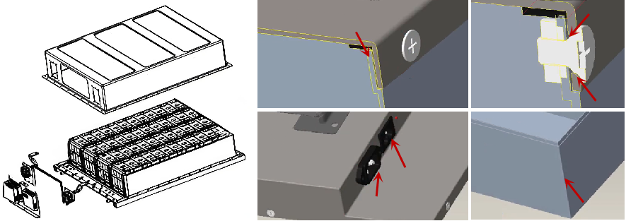
Figure 1: Schematic diagram of the energy storage pack box and key areas of focus in the sealing design (e.g., marked with red arrows)
As shown in the figure above, find out where potential leaks may occur:
l Multiple parts connection points, such as: the assembly interface between the upper cover and the lower box, the installation interface between the high and low voltage connectors and the box, the installation interface between the exposed components and the battery box, etc.
l If bolts are used for connection, there may also be a risk of leakage at the installation and fixing point, such as the electrical interface and the front panel installation interface of the box.
l There must be no holes or gaps in the upper cover and lower body of the box to ensure the sealing and protective performance of the box.
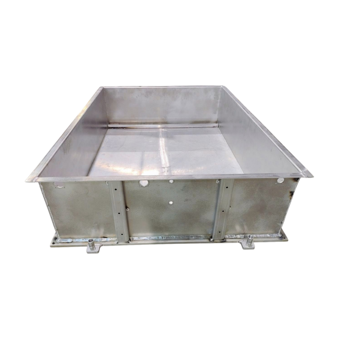
Figure 2: Immersion liquid cooling lower box (sheet metal frame + aluminum liquid cooling bottom plate)
2- Sealing design of the installation interface between the upper cover and the lower box
The upper cover can generally be divided into two types: flat type and special-shaped type. Their structural characteristics are also different. For example, SMC composite material, aluminum, no matter what material, in order to reduce the complexity of the self-sealing structure, the upper cover of the battery shell The cover is usually of one-piece design. In addition, the opening requirements of the upper cover should also meet the requirements of the interface, and should be independent of the sealing interface to reduce the impact on the battery pack sealing. The upper cover seal design generally follows the following principles:
l The integrated parts design is adopted to avoid the design of separate parts, thus ensuring the stability of the "self-sealing" performance of the upper cover.
l The positioning holes and positioning features are designed on the edge of the upper cover (outside the sealing interface between the upper cover and the lower tray).
l The sealing interface between the upper cover and the lower box body requires the matching surface to meet the "uniform" and "continuous" sealing requirements.
At present, the mainstream solutions for the lower box of the energy storage pack are: sheet metal box + liquid cooling plate, die-cast box + liquid cooling plate, profile integrated box, die-cast integrated box, etc. Among them, the profile integrated box and other solutions In contrast, it has the advantages of good flow channel bearing capacity and low mold opening cost, and is widely used. The choice of welding process has a great influence on the sealing performance. For weldments of different materials and thicknesses, choosing a suitable welding method can effectively improve the weld quality to ensure the overall strength and sealing performance of the system.
In addition, the sealing design of the lower box should follow the following sealing principles:
l Closed section profiles are used for frame construction, and self-sealing linear connection technology, such as CMT welding technology, is used at the joints.
l Battery trays made of aluminum profiles need to be designed with one or more continuous layers of sealing colloid.
l In the case of an integrated liquid cooling plate in the lower box, it is necessary to consider using colloid seals or self-sealing linear connection technologies, such as FSW friction stir welding technology.
l The sealing interface between the upper cover and the lower box body needs the matching surface to meet the "uniform" and "continuous" sealing requirements. If necessary, the sealing interface should be machined and polished.
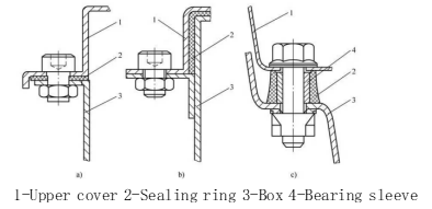
Figure 3: Common sealing forms between the upper cover and the lower box
Usually, the upper cover and lower box of the energy storage Pack box adopt a bent flange and a sealing gasket design, as shown in Figure 2. The upper cover, lower box body and sealing gasket are fully compacted and coupled by fastening bolts to ensure that the Pack box meets the relevant requirements of IP67.
3- Sealing design of electrical and communication interfaces and the front panel installation interface of the lower box
The front panel of the box (as shown in Figure 3) is machined with holes on the extruded profile for installing electrical and communication interfaces to achieve functions such as current transmission, communication interaction, and safety control.
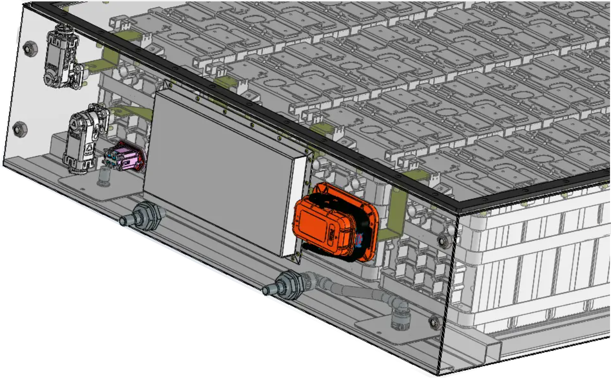
Figure 4: Electrical, communication interface and lower cabinet front panel installation interface
The air tightness of the installation interface between the box and the electrical, communication and other interfaces shall follow the following principles:
l The interface shape is designed to be streamlined to reduce the possibility of gas and liquid accumulation and penetration at the interface.
l Precise alignment avoids gaps caused by misalignment of interfaces during installation.
l Pre-seal the interface before installation and add anti-vibration pads or sealants to enhance the initial sealing effect or reduce sealing failure caused by vibration.
In addition, in terms of the selection of fasteners, high-strength, high-torque fasteners are used, and they are tightened multiple times during the installation process to ensure the tightness of the interface. For example, if a butt-weld nut is used, its characteristic is that it can be directly connected to the wall hole of the connected part (the front panel of the box) for butt welding. This structural design can significantly improve the airtightness of the connection part.
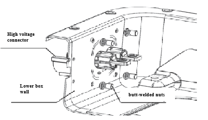
Figure 5: Using butt-welded nuts to increase airtightness
4-Seal selection
Seal design and selection are critical as they directly affect the reliability and service life of the system. The following are key factors to consider when designing and selecting seals for energy storage liquid cooling systems:
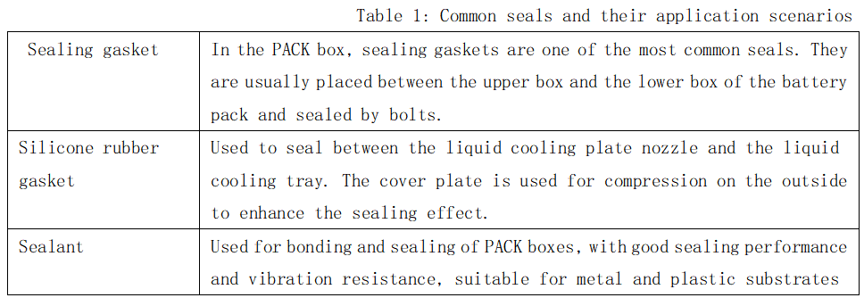
l The sealing material must have certain chemical and pressure compatibility, and be able to withstand the system operating temperature range, including high and low temperature environments. The material selection of the seal depends on the use environment and service life requirements. Common sealing materials include rubber, polytetrafluoroethylene (PTFE), nylon, metal, etc.
l Leakage freedom: The seal must be able to adapt to the slight deformation that may occur in the system during operation to ensure good sealing effect under various working conditions. Generally, the deformation of the gasket should be greater than 30% and less than 60%, and the sealing interface pressure should be greater than 30kPa.
We will regularly update you on technologies and information related to thermal design and lightweighting, sharing them for your reference.Thank you for your attention to Walmate.