
Communication and sharing promote growth
Joining Hands for Development!

In order to cope with market demands such as large spans, fast iterations, and rich product lines, while ensuring cost reduction, efficiency improvement, and quality assurance, for the automotive industry, product standardization - vehicle platformization is undoubtedly a good strategy. Through battery platformization, the same battery pack solution can be matched for different models, or battery pack solutions composed of the same type of battery cells and similar structures can be matched. This means that as many parts as possible can be standardized, which can shorten the development cycle, save costs, streamline production lines, and improve production efficiency.
ONE:Battery Platformization
The battery platform solution is conducive to the overall planning of products, cost reduction and optimization of production capacity. According to the battery platform strategy of the vehicle platform, it is necessary to consider the intersection and bandwidth of the requirements of each model of the platform, and use as few batteries and battery solutions as possible to be compatible with as many models as possible. In the architecture development of pure electric projects, it is crucial to reasonably arrange the integrated power battery pack. Specific work elements include power and power performance requirements, collision safety, layout location and space, etc.
1-Spatial size boundaries and battery cell standardization
l Available battery pack locations
At present, the mainstream power battery layout is under the floor, including under the front seats, under the rear seats, in the middle channel and at the footrest. This layout can maximize the available area, help lower the center of gravity of the vehicle, improve the handling stability of the vehicle and optimize the collision force transmission path.
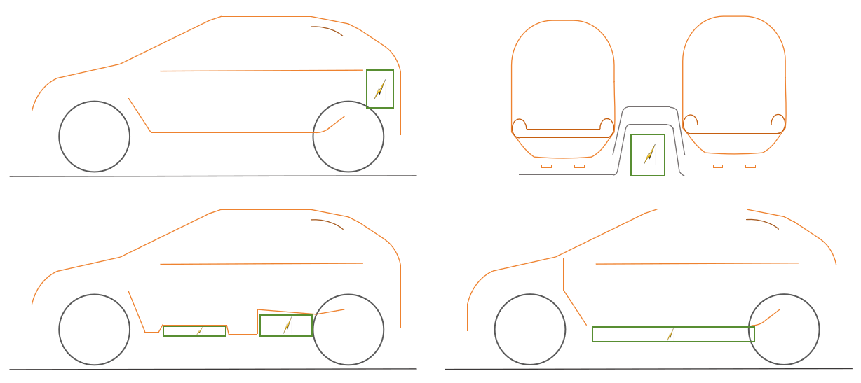
Figure 1: Battery pack layout during the development of electric vehicles
l Evolution of battery pack space layout
Split battery pack: A split battery pack space layout is adopted, such as the JAC Tongyue series. The energy module consists of two battery packs, one placed at the original fuel tank position, and the other placed in the trunk where the spare tire is stored.
In addition, engineers are continuously exploring usable space within the original architecture of fuel vehicles, resulting in battery pack layouts appearing in "工" (gong), "T," and "土" (tu) shapes.
This type of design is a minor modification of a traditional fuel vehicle. The space is very limited, and the volume and weight of the battery pack that can be loaded are very limited, so the capacity is difficult to increase and the cruising range is not high.
Integrated battery pack: This is a new product design concept. The design of the entire vehicle revolves around the core component - the battery pack. The battery pack is modularly designed and laid flat on the vehicle chassis to maximize available space.
l Battery pack installation point layout
Reasonable layout of the battery pack is crucial, and the limiting factors in the design are ground clearance, passability, collision safety, power requirements and many other aspects.
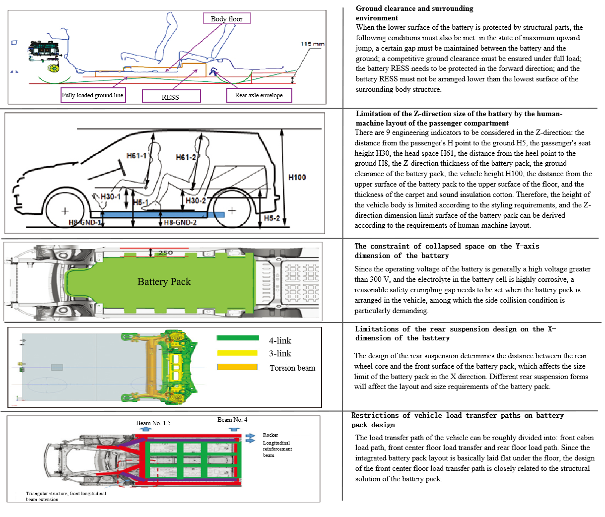
Figure 2: Battery pack size design constraints
The vehicle platform needs to define the category, level and positioning of each vehicle model within the platform, and then determine the size and wheelbase of the vehicle. The vehicle layout decomposes the size envelope of the battery pack in the X, Y and Z directions according to the vehicle space. The battery needs to be arranged within the given envelope of the vehicle to ensure that there is no interference between the various systems of the vehicle. The curb weight index can decompose the system quality requirements of the battery pack.
In terms of battery size, the design of power battery packs cannot avoid rigid reference indicators such as vehicle space and curb weight, which means that there is a threshold for the design of battery cells. Constrained by this threshold, the battery cell size will be concentrated in a certain range, such as: the length of square battery cells ranges from 150-220mm, the width ranges from 20-80mm, and the height ranges around 100mm. The changing trend of battery cell size specifications is the result of the complementary relationship between vehicle platformization and battery standardization.
However, the battery platform strategies, vehicle models and understanding of standardization of various automakers are different, resulting in significant differences in the current product solutions. For example, BYD's standardization strategy is to fully replace the blade battery, the size of which is locked at 960*13.5 (14)*90 (102) mm, and the single cell voltage is 3.2/3.3V.

2- Development of Endurance Boundaries and Battery Capacity Solutions2- Development of Endurance Boundaries and Battery Capacity Solutions
The power battery provides energy for the vehicle to travel: battery capacity, discharge depth, and energy density affect the amount of power available. In order to meet the needs of different models, the difference in power consumption of models has become an important concern. The vehicle's cruising range will be affected by factors such as electric drive, battery, curb weight, wind resistance, mechanical resistance, low-voltage power consumption, and energy recovery. The possibility of sharing battery solutions between models with large differences in power consumption is weak, so it is necessary to develop personalized battery power solutions, including battery size, quality, power, and power performance optimization to meet the requirements of cruising performance.
Under the constraints of the pure electric range of the vehicle manufacturing platform, the net discharge required by the battery will be affected by the power consumption of different models. It is necessary to confirm the power consumption distribution of each model on the platform in order to further convert the power consumption bandwidth into the battery demand distribution, and then determine the battery power plan required by the platform.
3-Power performance boundary
The dynamic performance of the whole vehicle includes the power performance under acceleration conditions, constant speed conditions and power preservation conditions at different SOCs and ambient temperatures. The variables corresponding to the battery are the power-voltage characteristics of the battery at different SOCs and temperatures. The power of the battery corresponds to the power requirement of the vehicle's power system, and the voltage corresponds to the rated voltage requirement of the drive motor.
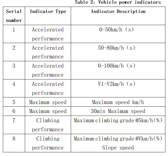
Generally, the evaluation of battery solutions for the entire vehicle platform starts from the acceleration time of 100 kilometers at normal temperature and high power and its battery indicator decomposition, and gradually extends to the battery indicator decomposition over the entire range and under all operating conditions.
SECOND:Battery box development
1-Battery integration and modularization
Optimize the design of battery modules, improve the integration and modularity of battery packs, reduce inactive components, and increase the energy density of battery packs.
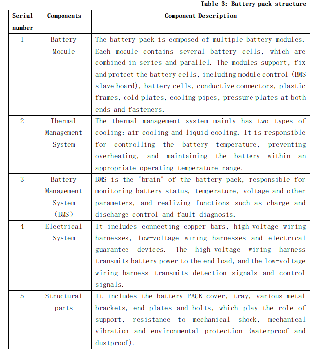
Currently popular battery pack integration technologies include CTP, CTB, CTC and other forms. The shape, material and combination of parts have changed with the advancement of integration technology. The overall direction is integration and integration. By reducing the number of independent parts and using one large part to replace several parts, larger and more functional components are formed.
2-Battery box design
The battery case is the carrier of the power battery system assembly, plays a key role in the safe operation and protection of the product, and directly affects the safety of the entire vehicle. The structural design of the battery case mainly includes the selection of shell materials for the upper shell, lower shell and other components of the battery case, and the selection of manufacturing process solutions. The upper cover of the battery case mainly plays a sealing role and is not subject to much force; the lower case of the battery case is the carrier of the entire power battery system product, and the battery module is mainly arranged in the lower case. Therefore, there must be structural measures such as embedded grooves and baffles inside the battery case to ensure that the battery module is reliably fixed when the vehicle is driving, and there is no movement in the front, back, left, right, up and down directions, so as to avoid impact on the side walls and upper cover and affect the life of the battery case.

Figure 3: Battery lower box solution, a-skin frame, b-FSW welding + frame, c-FSW welding + frame
l Battery pack installation point structure design and connection fixation
The battery pack installation point usually adopts a mounting beam structure, which runs through the front and back, and the front end is connected to the front cabin longitudinal beam to form an effective and coherent closed beam structure. The installation points are reasonably arranged according to the weight distribution of the battery pack. The battery pack and the vehicle are fixed in various ways, including bolt fixing, mechanical fixing + adhesive joint hybrid connection, snap-on connection, etc.

Figure 4: Battery pack layout and installation section
The power battery pack is generally installed on the vehicle through multiple lifting lug structures. In addition to the large weight of the power battery pack itself, the lifting lugs must also withstand the road excitation brought by the vehicle's movement, such as stone roads and deep potholes. Such durable working conditions and misuse conditions place higher requirements on the strength of the lifting lug structure.

Figure 5: Different lifting lug connection solutions: a Welded lifting lug b Aluminum extruded frame lifting lug
l Battery box safety and protection structure
Mechanical strength and protection: The battery box should have sufficient mechanical strength to protect the batteries inside from mechanical shock and impact. The battery box needs to be able to withstand vibration, extrusion, and mechanical shock to ensure the safety of the battery under various conditions.
Collision protection: The design of the battery case must take collision safety into consideration, especially for side collisions and bottom collisions. It is usually made of aluminum or steel and connected to the lower tray through an outer frame to provide structural rigidity and enhance collision energy absorption capabilities. In addition, appropriate collision absorption structures should be designed to prevent deformation of the battery case and damage to the battery cells.
Waterproof, dustproof and corrosion-resistant: The battery box needs to be waterproof and dustproof, and usually uses IP67-level sealing gaskets to ensure airtightness. In addition, anti-corrosion measures should also be considered, such as spraying PVC coating on the outside to enhance corrosion resistance.
Explosion-proof and pressure relief design: When a battery explodes, the energy should be released in a concentrated and directional manner through devices such as balanced explosion-proof valves to avoid entering the customer cabin. In addition, explosion-proof measures (such as partial structural destruction) should be taken to prevent the overall rupture of the equipment.
l Sealing design
The design of the sealing surface between the upper cover and the lower case of the battery box plays an important role in the sealing performance, and its design needs to be designed together with the battery box structure and the sealing ring. The sealing surface should be kept in the same plane as much as possible to avoid too many curved structures. Since the upper cover and the lower case are connected by bolts, a large number of bolts are used, so it is particularly important to ensure the coaxiality of the holes. While arranging the bolt hole positions reasonably, the position dimensions should be as round as possible and arranged symmetrically in the X and Y directions. The selection of the number of connecting bolts needs to be comprehensively considered based on the level of sealing and the amount of disassembly and assembly workload.
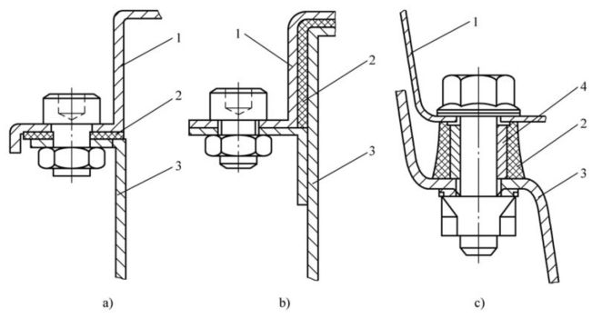
Figure 6: Upper and lower box sealing design, 1-battery upper cover 2-sealing gasket 3-battery lower cover 4-metal conduit
l Electrical safety and short circuit protection
Connection reliability: The connectors inside the battery box should have the correct polarity connection to ensure the overcurrent capacity of the battery box and the reliability of the electrical/mechanical connections, including relaxation measures, etc.
Electrical insulation and voltage resistance design: The module design adopts double insulation protection. The battery cell itself has a layer of battery cell blue film and a battery cell top patch to meet the insulation and voltage resistance requirements. Insulation and voltage resistance protection is set between the end/side plate and the battery cell, and between the battery cell and the bottom mounting surface.
l Thermal management design
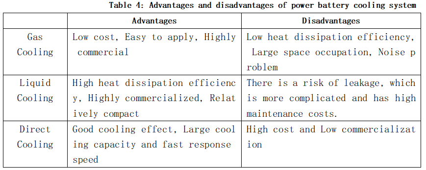
Battery thermal management development runs through the entire cycle of battery pack system design and development, including the design of battery temperature control, cold plate, piping system, etc. The main goal of battery thermal management system design is to ensure that the battery system operates at a relatively suitable operating temperature through heating or cooling control while considering space layout, design cost, lightweight, etc., while reducing the temperature difference between cells to ensure consistency.
We will regularly update you on technologies and information related to thermal design and lightweighting, sharing them for your reference.Thank you for your attention to Walmate.